
Small Prototype Engineering
2024-02-03 Devboard
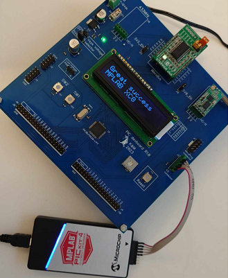
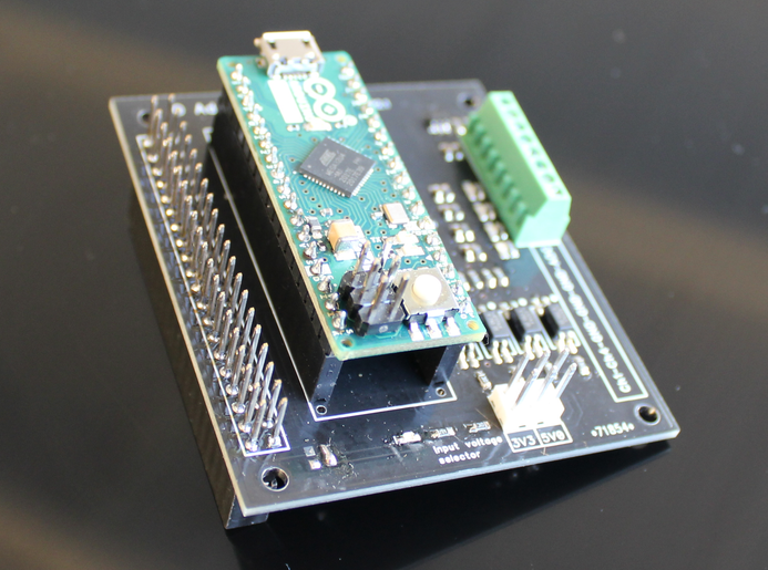
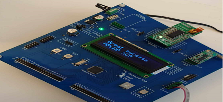
MikroE decided several years ago to stop supporting their C compiler which i find sad but this forces me to learn and use a new compiler which will give more benefits. It felt naturally to choose Microchips own MPLAB X. I devloped with a friend a simple developmentboard for PICs to experiment on. Unfortunatly we managed to choose a older PIC that is not for new design but it will do for now
2023-09-11 DIY ESD gun
Often when designing a board i would like test if it can withstand ESD. Buying one is not an option and using a piezo electric lighter will just give a rough estimat.
My goal was to design a ESD gun with following specifications:
- Contact discharge only
- 2-8kV output with 1000V/step
- Positive discharge
- Single pulse mode
- 10 pulses @1Hz mode
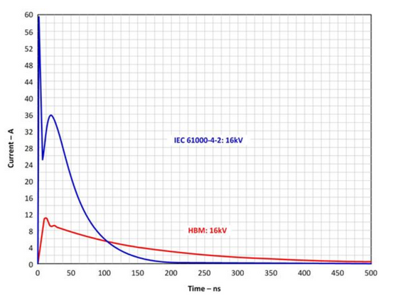
- Discharge curve as close as possible to ESD standard IEC-61000-4-2
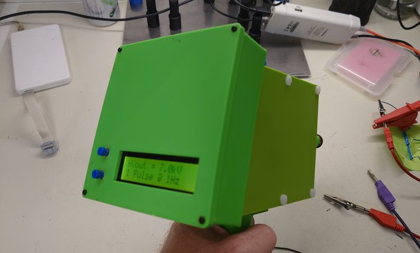
Now when the gun is finalized it has the following features:
- Both contact and air discharge
- 7 and 8kV output with 1000V/step
- Positive discharge
- Single pulse mode
- 10 pulses @1Hz mode
IEC-61000-4-2 standard claim that a capacitor of 150pF shall be fullly charged and then discharged into the DUT thru a 330ohm resistor!
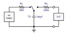
The concept is to use have a HV (high voltage) module and to use this to charge the capacitor. The primary voltage to the HV module is powered from an adjustable voltage regulator. To controll the regulator a digital potentiometer is setting the feedback.
When the capacitor is fully charged the HV module is disabled and at the same time the energy is swithed to the DUT thru a HV relay.
At first atempt i tried to design the HV module and controll it with a MCU but i never achieved more than 1.1kV output at most. Realized that im not really in to HV designs.
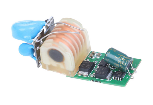
Purchased a complete HV module on EBAY for 3USD and it just works as expected.
The biggest downside with this HV module is that it outputs just below 7kV at startup. Therefore i cannot have lower output voltage than 7kV. The HV relay is specified up to 8kV so these two parameters sets the output span. I might lator on try to find a module with lower output.
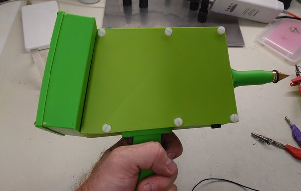
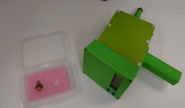
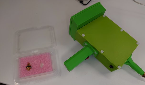
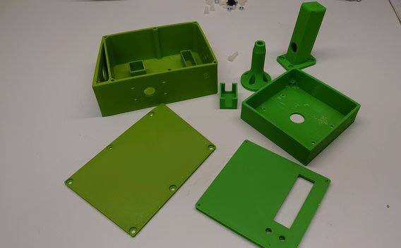
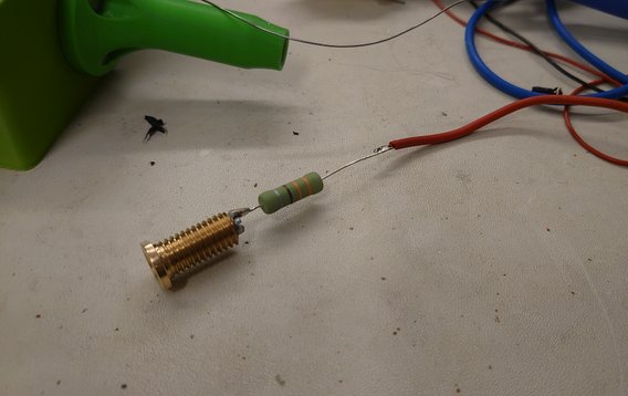
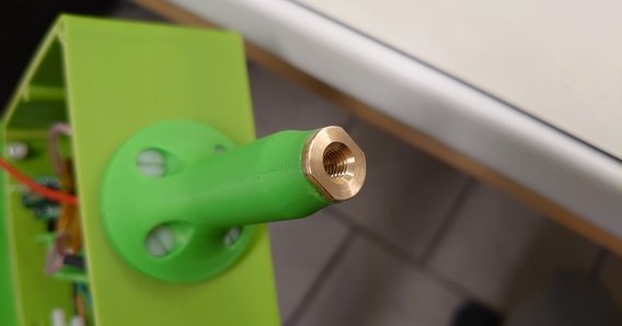
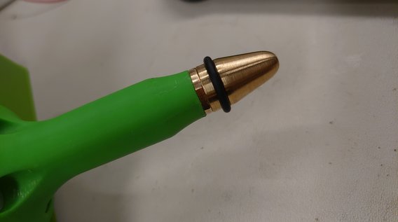
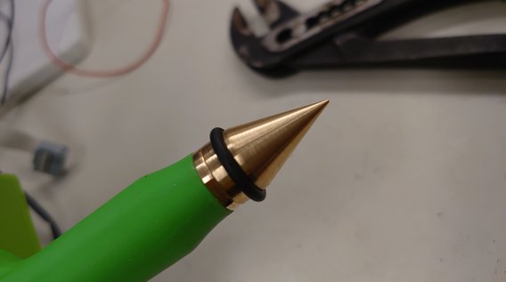
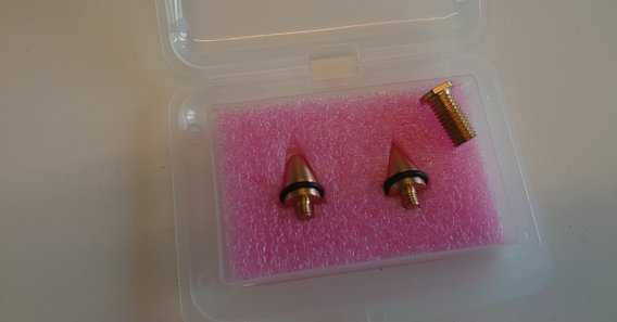
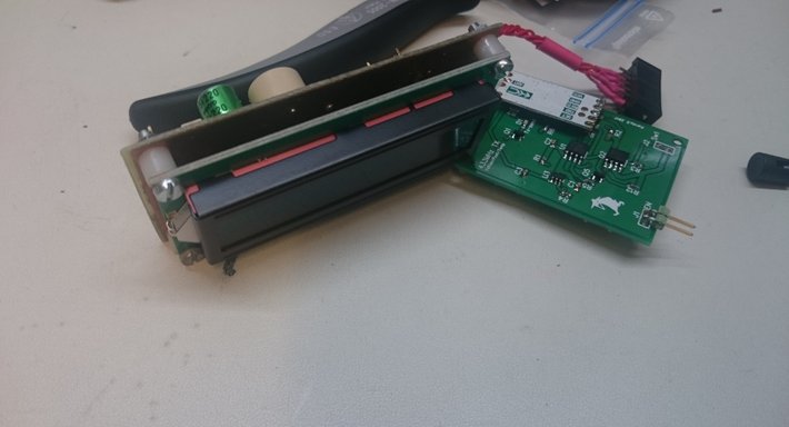
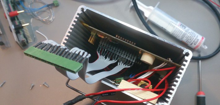
The casing is 3D printed and consists of totally 7 part. For isolation teflon screws are used. A collegue is really good at mechanical work and he made me a couple of great tips. One for contact and one for air discharge. The 330ohm dirscharge resistor is housed in the barrel of the gun

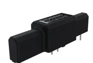
Biggest issue during the development is that i experienced alot of contact bounces at each discharge. Contact bounce at 7kV are almost impossible to sort out. Even my computer screen restarted time to time. The first relay i used was a Pickering 67-1A-5/2D and it did not work at all.
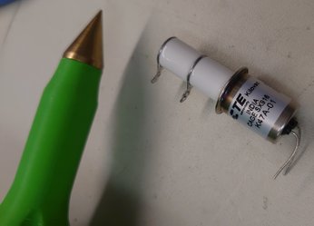
I solved it by using a real vacuum relay and found the TE-Connectivity Kilovac K47A-01. Due to the vacuum there will be no or very little arching and electrical fields.
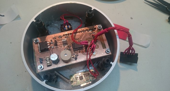
All HV components are fitted in the main casing. One issue whit the Kilovac relay was that sometimes at disharge it arched over to the coil pins. The solution was to isolate the coil connectors with epoxy glue!
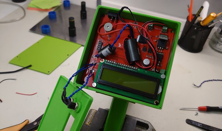
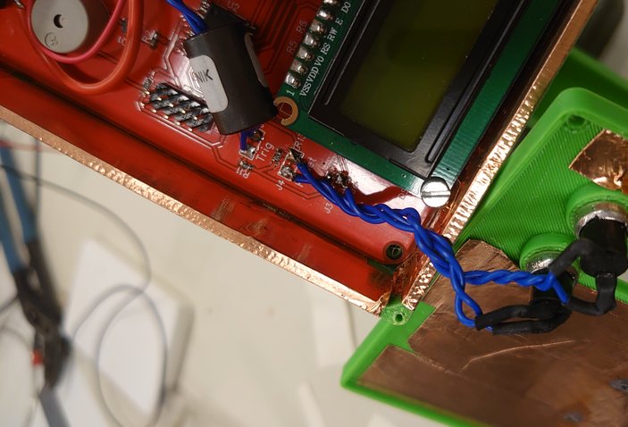
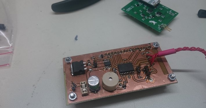
On the mainboard the MCU is fitted as well as display, buzzer, 2 buttons, local power, digital potentiometer and the adjustable regulator to the HV module primary side. As can be seen there are som ferrites around the cables but i really don't know if they do any good. I had them and thougt " well they can't hurt"
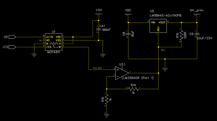
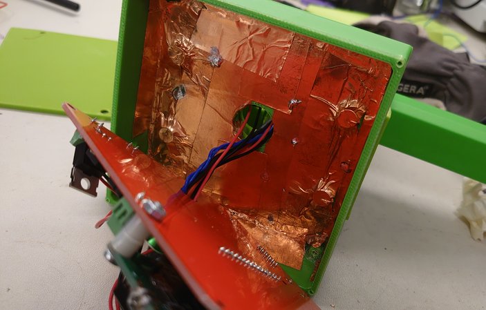
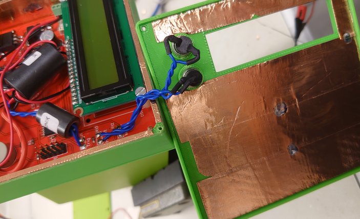
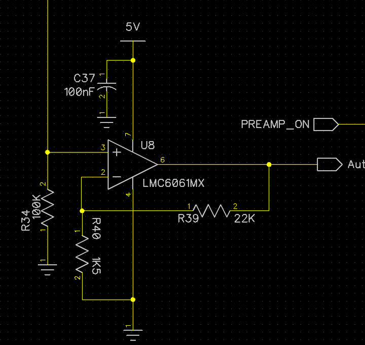
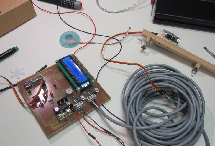
The more i tested the gun teh more i realized that there were issues with stability. Mainly the display communication was disturbed and also the digital potentimeter used for setting output voltage lost it settings. As seen below the wiper on the POT sets the adjust pin on the voltage regulator. The OP is used as buffer and also to be able to manipulate the voltage level if needed. Added copper tape inside tha casing as an atempt to create a Faraday cage and also introduced a function in SW that resent the latest settings to the display and to the digital POT. The gun is stable after the introduced fixes!
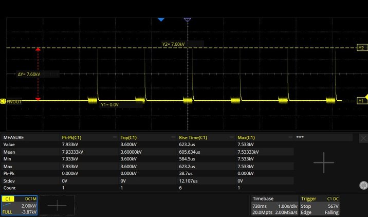
Final measuerment. As can be seen the discharge curve is not fully identical to the standard but as a hobby isntrument it will do quite fine. Also the BW of the diffprobe and my oscilloscope might have some impact on the measured signal
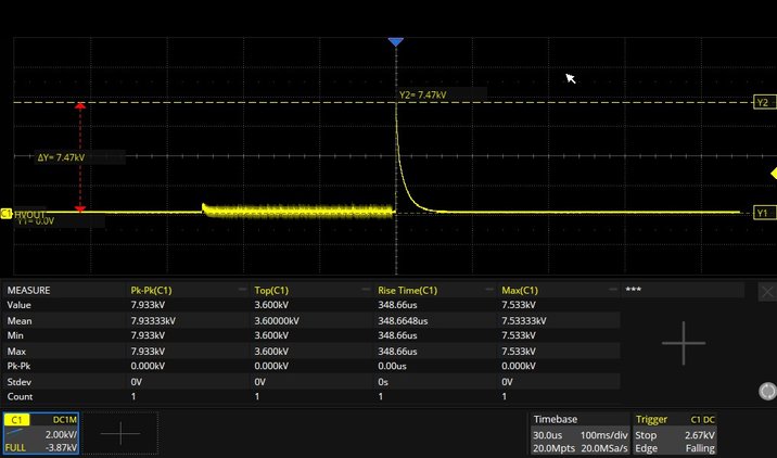

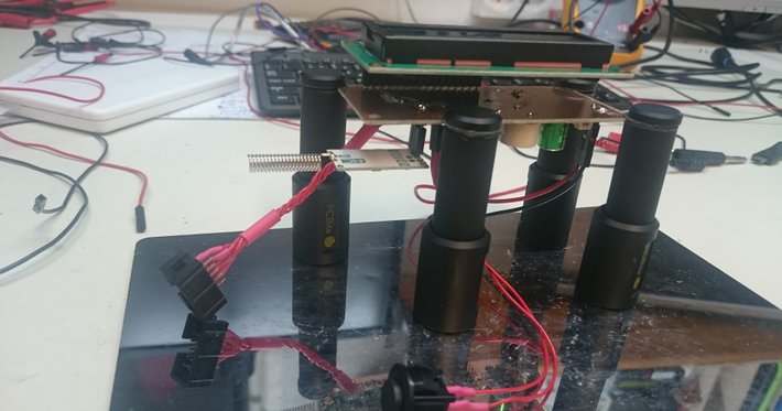
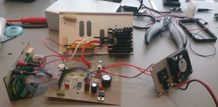
A real early test run with the gun. Here i actually dont use the HV Relay but only enabling the HV module.
2023-01-15 NanoIoT33 new rev
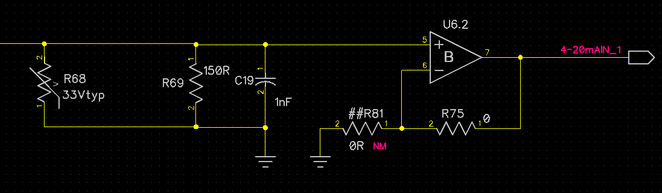
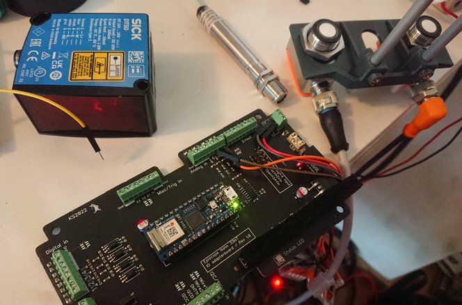
New updated version with current inputs för the industry standard 4-20mA. Have never worked with this simple signal interface before and of course things went wrong. The idea is to drive a current thru a known resistor and then let a ADC read the value thru an OP configured as a voltage follower. I choose 150ohm which will give around 3V at 20mA. The conversion itself works as designed.
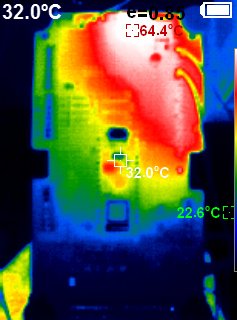
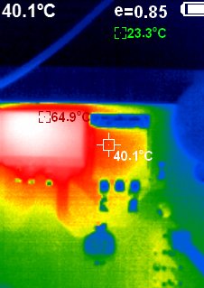
Noticed on two boards that something was wrong and that input seems to b shortcircuited. After some troubleshooting it was clear that the +input on the OP was burnt and was around 1,5ohm. But why?
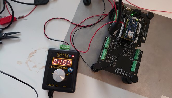
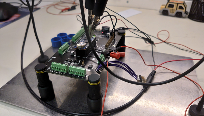
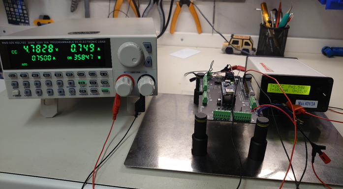
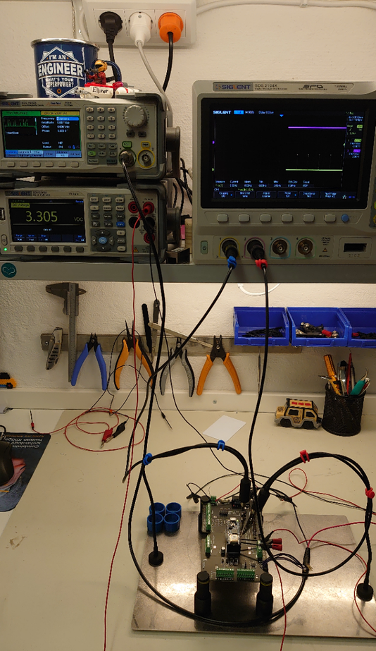
Well the reason was found quite fast. I used a testinstmrument that can simulate the input current. If this testinstument is unloaded on the oututput it supplies 24Vdc out.
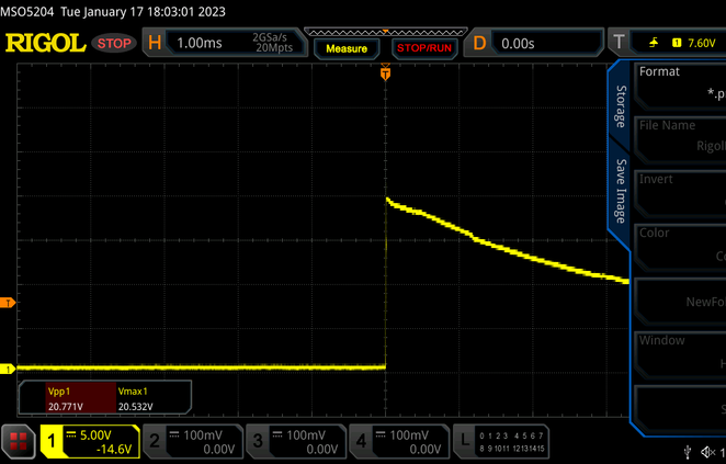
So when connecting the probe from the instrument to the input there will shortly be an overvoltage transient of around 20Vdc into the OP which has a max tolerance of 6V. This will damage the input. I don't know if real sensors work the same and not having this high out voltage initially bet it's better to protect the input. The testsetup below shows the otherwise great testinstrument which can be purchased for around 25USD.
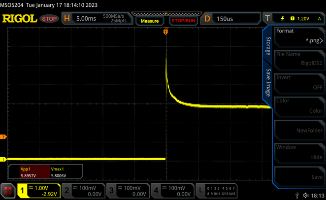
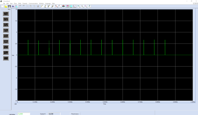
Issue is solved by putting a 3.3V zenerdiode in parallel with the input and clamping the initial high input voltag. Scope pictures below show that input is around 20V berfore and around 6V when diode was added. The zener is a bit slow when clamping and therfore it goes higher then 3.3V but it works fine in this application.
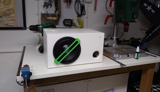
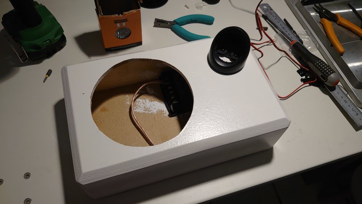
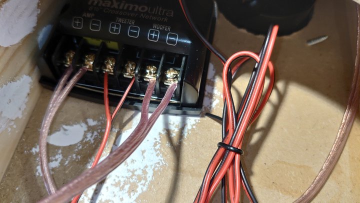
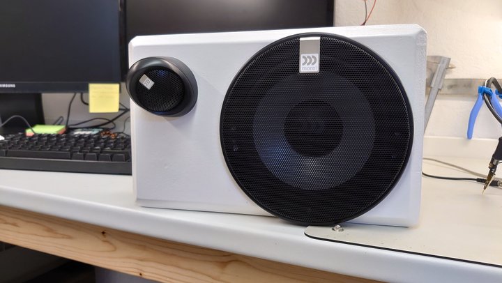
2022-12-12 6,5" active subwoofer
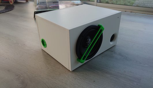
Adding a small active subwoofer to the previous project to handle the lower frequencies. Using the same same digital amp but configured as bridged mode to drive the subwoofer with 100Wrms.
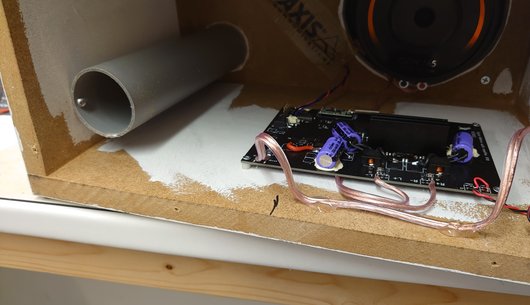
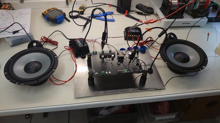
Did not have all the correct components in stock so I used what I had. The audio result is at the moment not as good as expected, would almost state it's bad. It feels lik the amp is to weak to controll the subwoofer. the base sound just weird and blurry. It does'nt really produce any high soundpressure either, but that could be caused of it's small size. I have never built a ported enclosure before so it might be the case that i have tuned the box badly.
Tried to play around with the DSP and if i narrow the frequency span i can filter out the blurry sound.
I will connect the whole system later on and see if i can tweak it to sound good enough later on. Othervice i'll try to experiment with the enclosure and the port length.


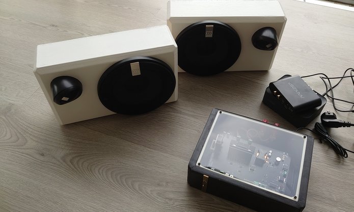
2022-10-11 Digital 2Ch amplifier
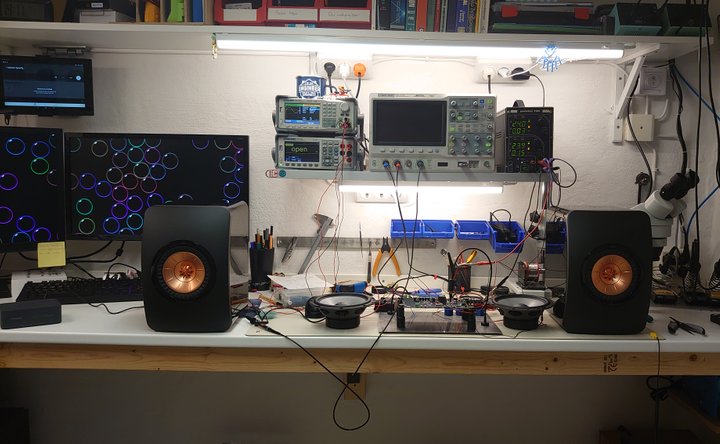
Have done a few amplifier projects but never did a class D amplifier which would be a fun thing to design. I have a room in my garden where it would be nice to play music, so this amp did fit this application. To really optimize the sound i will use a MiniDSP 2x4. The speaker are also home made and work excellent but will need a small subwoofer to sound as they should
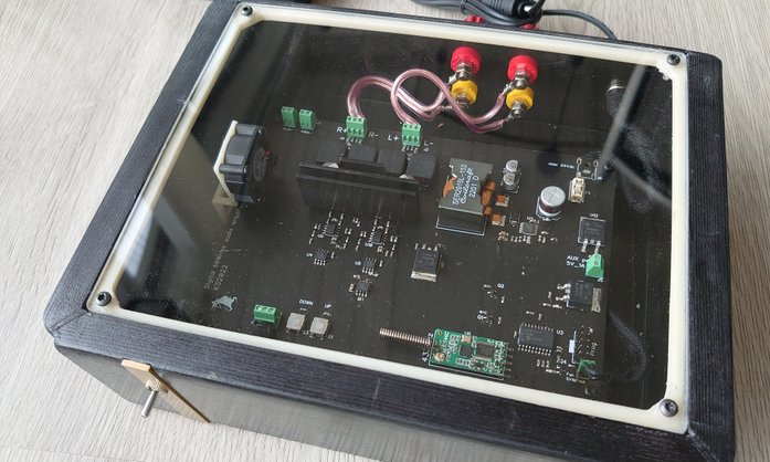
The amplifier features are
-Class D
-DCDC powersupply
-2Ch
-Autostart at detected incoming signal
-433MHz remote
-Digital potentiometers
-Temp controlled
DCDC power supply.
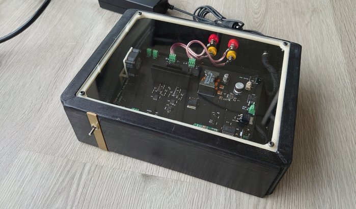
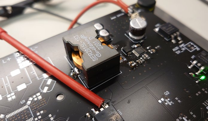
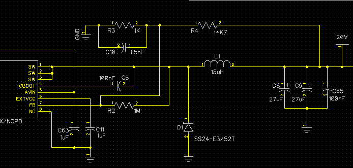
As a part of the design i wanted to learn a bit more about high power buck design. So i designed a 60W 20V switched power supply.
I did use TI's webbench to design the power supply and reused their layout example. The design is based on LM2696. It calculates allt the component values and it can optimze for BOM, price or efficincy.
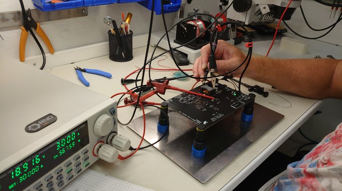
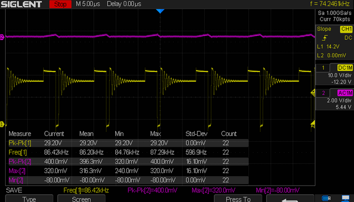
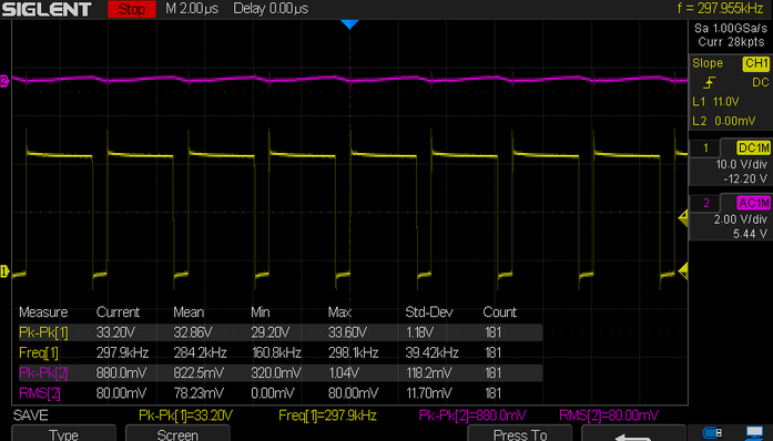
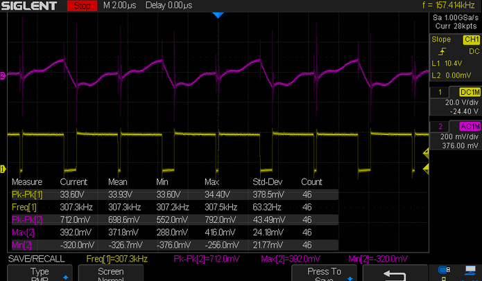
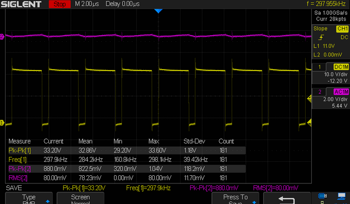
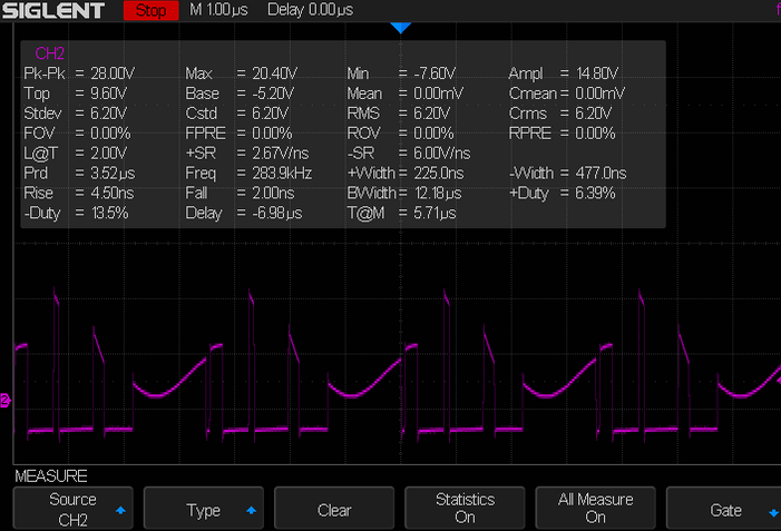
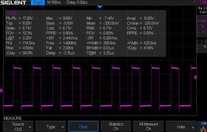
Measurements below show the output loaded with 100mA, 500mA and 3A which is maximum aoutput current of the buck controller. Ch1 is connected to the switch node and Ch2 to the output. 24V input voltage!
Class D amp
TPA3116 is a small class D amp that will work with amost no heat sink. It has extremaly high efficiency and small footprint. Its pretty straightforward to use it and there is alot of information on how to concect it as with all switched electronics care must be taken when drawingt the layout. One thing to have in mind is that the inputs of the TPA3116 are balanced (differential) but most home aduio equipment are unbalanced (common mode).
This was solved by a specific TI audio circuit OPA1632. Input gain can also be adjusted here to fit the power stage!
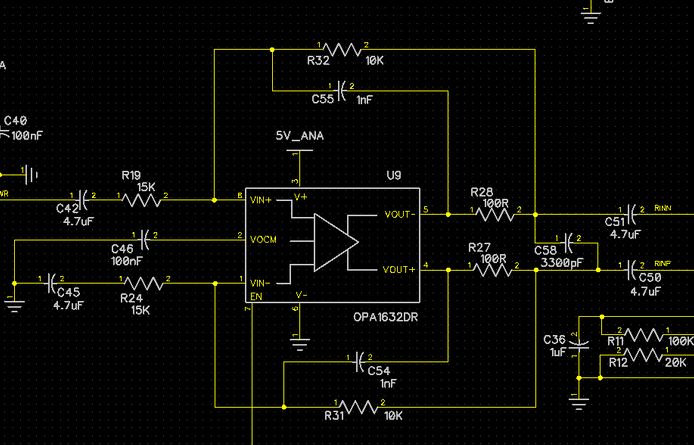
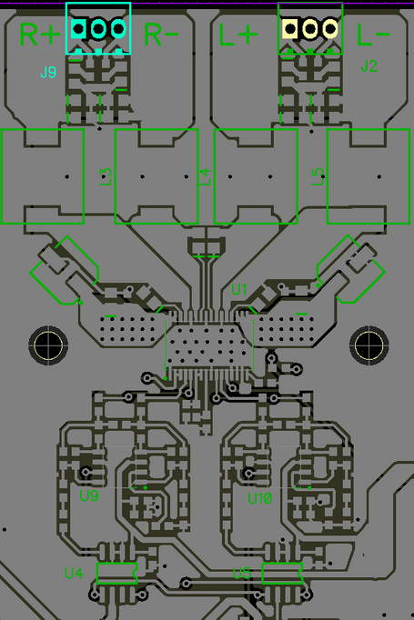
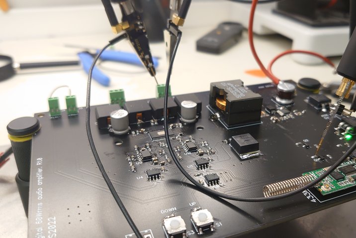
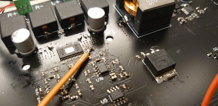
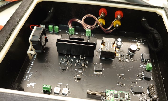
The layout was done very carefully and i used the layout of an evaluation board for the TP3116 as reference. On the bottom there is a ground plane and a power plane connecting power to the IC and big capacitors.
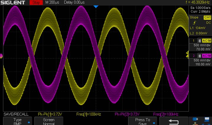
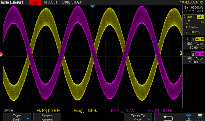
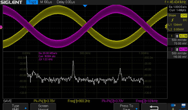
Output is measured with input signal of 1Vpp/1KHz. No switching ripple can really be found at the outputs.
Notice that the output swing is 3,64Vpp+ and 3,7Vpp- for the left channels and 3,7Vpp for both +- on the other channel. The difference of 60mV is quite small and cannot be picked up by the ear.
Also a conducted FFT was meausred on the L channel. I'm not quite sure how well the scope actually performs this it was mostly done of interrest.
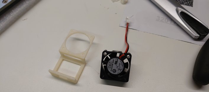
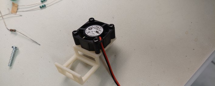
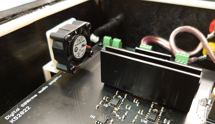
Temperature controll, autostart, digital potentimeters and remote controll are all managed by PIC16F18346. It measures the temperature locally att the buck controller IC and the audio amp IC. if any of the temperature limits are exceeded the MCU will shut down the amplifier by controlling mute and shutdown pins. There is also a small fan that can cool the heatsink for the audio amp i temperature is increasing. For the remote controll the HC11 433Mhz module is used and will controll volume, mute and power ON.
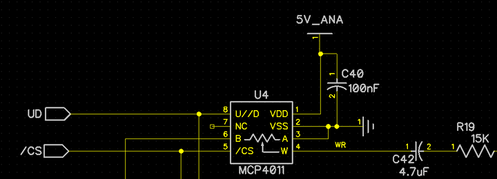
For volume controll im using 2pcs 64 step digital potentimeters MCP4011 wich are both controlled by the mcu thru a simple interface with. Everytime the amplifer turns on the volume is set to a default level.
Finally the autostart is made of a single OP that connects to a ADC input of the MCU. If ther is a input signal it's detected and enables the whole board in proper order.
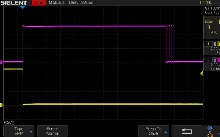
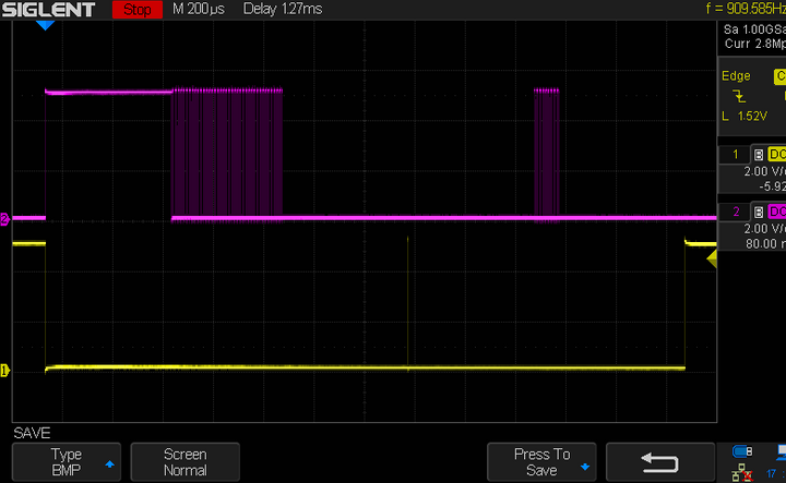
Below shows the protocoll for one volume down step. And also the command for defalt star volume, first it lowers the sound to minmum by sending 70 times the lower command. Then it will raise the volume by 15 steps or so.
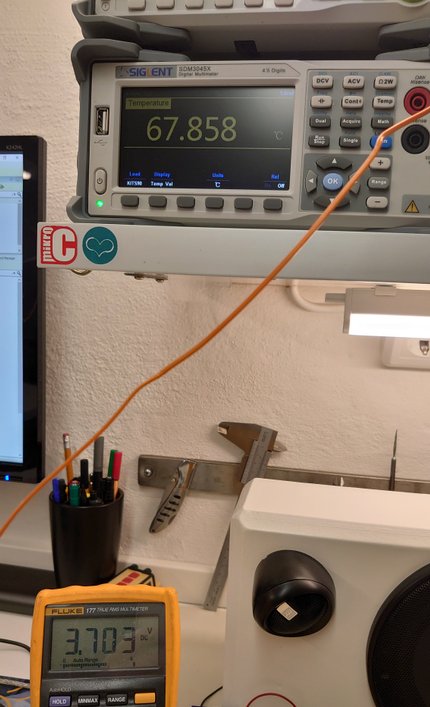
Setting and calibrating the temperature controll and limits
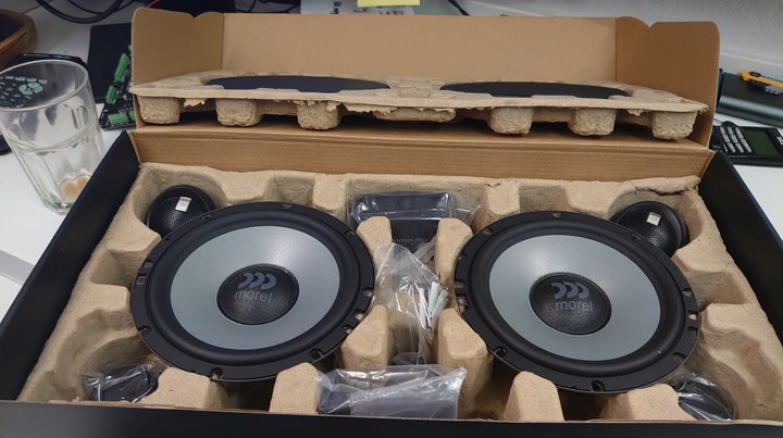
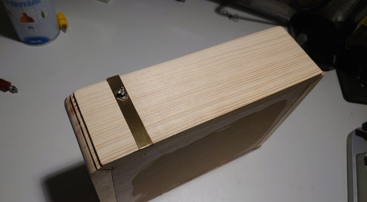
Finally the speakers and amplifier casing was built. During development i tried a couple of different speakers and the best result was with my hifi speakers KEF-LS50, they sounded great and hade excellent base response and no dsp or external sub was needed. But the speakers i intended was the 2 way kit from Morel Ultimo2. They had hard time with base response even when i tried the DSP. There will be an added subwoofer in the future.

2022-07-30 Nano33IoT released
Nano33IoT has now been ofificially published and it has been recieved well. Now some more updates and improvements will be implemented to be produced in a bigger batch

2022-06-09 Nano33IoT_adapterboard
My 2nd design for Episcope.
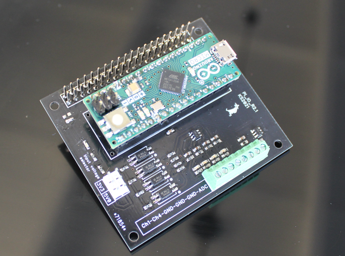
This adapterboard is intended to house both a Raspberry Pi 4 and a Arduino nano IOT. It will act as a inteface to the outside world with high protection level. The board is desigend to fit into a industrial casing that will be sealed.
One thing i used in the design was a small DCDC power module from Traco which has almost the footprint as the standard TO220 linear regulators. They are expensive but works very well with low heat dissipation at even medium to high load.
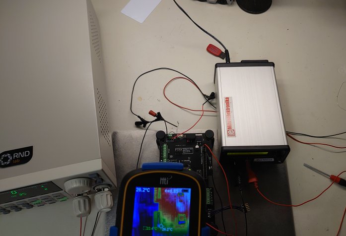
Heat tests were performed at 40degC ambient. All power nodes were loaded externally with electronic loads.
There was a requirement to have some kind of external and independent watchdog that controlled the reset pin of the Arduino. It recieved a signal each minute from the Arduino and if this was not sent the WD issued a reset signal to the Arduino.
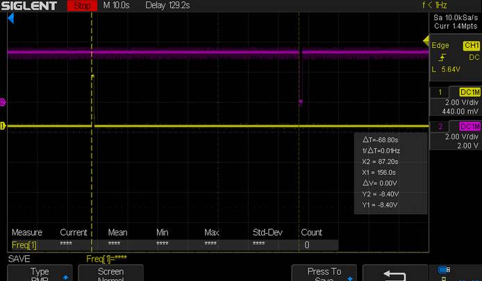
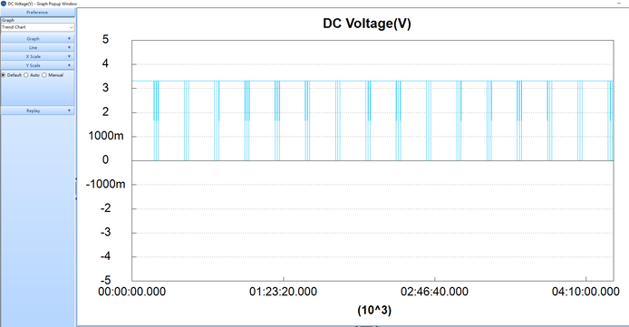
I tried to find some reset circuit but they are all made for shorter timeout delays. I therefore used a Pic12LF1572 and created a WD. To test the function i used my arbitary signal generator and created an output signal that sends out 14 pulses. One/ minute and each 1s long. After 14 pulses it will than wait some time so that the watchdog can send out 3 reset signals. The signal was verified both with oscilloscope and with a longer test using a multimeter with logging function.
Test signal created with Siglent waveform generator
2021-10-27 IO & ADC interface
Designed for Episcope a professionell IO and ADC adapterboard that works togehter with Raspberry PI4 and Arduino Micro with the formfactor of a Pi hat. It will be used in industrial enviroment for monitoring industrial equipment and has therefore high protection level against power transients and other disturbance. Of course the IO inputs are isolated for highest level of safety.
2021-09-23 Episcope
2 months ago i teamed up with a small company called Episcope and currently doing some freelancing for them.
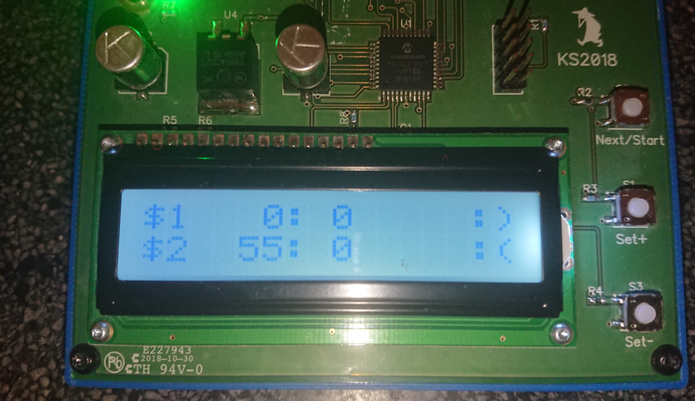
2021-09-17 Timekeeper
This is barely considered as a project but i needed a timekeeper/ counter since i've started doing some small scale freelancing. I needed a simple timer that i could keep track of time spent on project by just pressing a button. I also added so there is two separate counters for different jobs.
I made it real simpe using a old controllernoard from work that i designed but actually didn't work for the purpose so it was more or less useless. But it had some buttons, a pic controller and a LCD.
Perfect!
The project is straightforward so there is'nt much to say aabout it but it's a perfect time counter tool for the lab :)
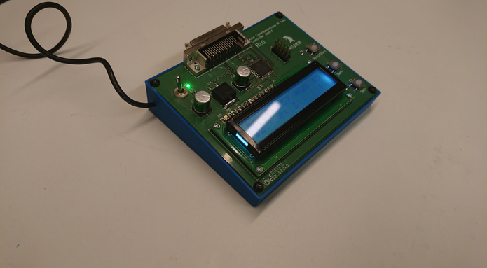
A really simple 3D printed case makes it easy to use
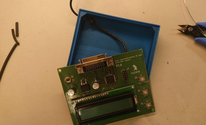
One issue with the code made me crazy. Often when power was toggled the display was showing the number 55 in the hour and minute section and i could not imagine why. I didn't understand where the number 55 came from.
I actually went to a electronics forum and asked what this might be. After some discussion a member found in the datasheet that for some reason every wright instruction to this PIC is initiated by writing HEX 55 for some reason. So what actually was going on is that when the code was writing to the eeprom the minutes and hours i sometimes toggled the power. When i timed it wrong the code had just written HEX 55 to the eeprom and was about to write the correct data but lost power. So 55 was then stored in the eeprom. I also discovered that i wrote to the eeprom when not supposed to. Correcting this and making sure to stop the counter before turning of the power solved everything!
From the PIC 16LF1937 datasheet
BCF INTCON, GIE ; Disable INTs.
MOVLW 55h ;
MOVWF EECON2 ; Write 55h
MOVLW 0AAh ;
MOVWF EECON2 ; Write AAh
BSF EECON1, WR ; Set WR bit to begin write

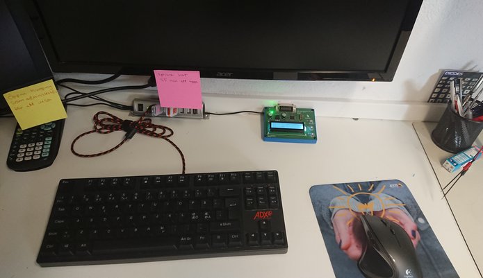
2021-04-03 Ljudbyggaren tests PhazeSpy
Ljudbyggaren is a professional car audio installer located in south of Sweden. PhazeSpy will be tested by Ljudbyggaren and the first test run seem to have been a success. For you who don't speak swedish he thinks the instrument is fantastic. During the design phase Ljudbyggaren has had input regarding requirement and functionality.
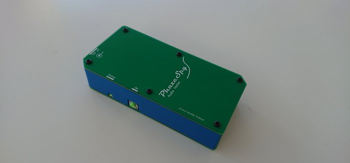
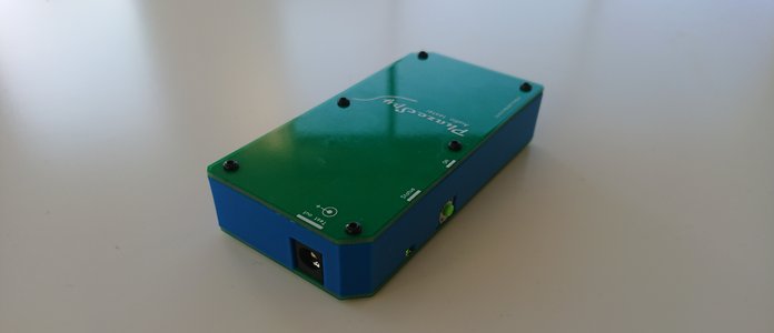
2021-03-22 PhazeSpy
PhazeSpy is a tool developed for car audio installers and professionals. When installing/ upgrading and troubleshooting car audio in modern cars you never know what cables you are actually cutting or connecting to.
Also on many occasions you need to identify which cable is connected to a specific speaker.
Newer cars have multichannels amplifiers and that amplifier is often located in the trunk. Most proffesionals use a small battery to "blipp" the cables and try to listen at the same time which speaker that pops. This works but there is always a risk that you actully "blipp" a sensitive signal cable and therefore damage expensive car electronics.
Also it's not practical to use a battery because you have to use a long cable when going around the car listenning and blipping at the same time.
PhazeSpy has some safety functions. It will detected if there is any voltage on the input of 0,4V and 1V inverted polarity. If there is no voltage present it will send out 5 short pulses of 25mW to measure the connected resistance. 1,5-9Ohm is considered as a valid speaker resistance. If this also is a pass it will send out a 100ms pulse of around 6.5W to move the speaker cone. This is audiable and therefore it's possible to detect which speaker is moving and the phase of the movement.
There are three user modes.
-First one is already described with the safety functions.
-The second is safety disabled and forced output pulses with 25mW 100ms.
-Third mode is also sfety disabled and forced output pulses of 6.5W 100ms.
Safety mode will sooner or later detect bad resistance due some speaker filter configuration. Therefore it's possible to run the audio tester in forced low or high power mode.
Auto-off turns of the tester after 20min.

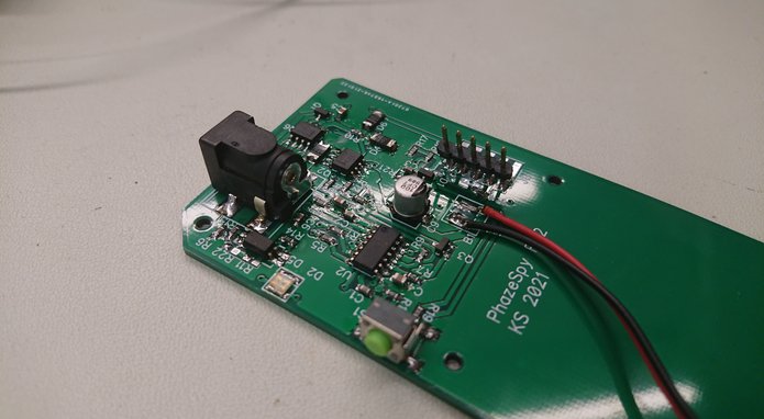
The design is kept as simple as possible. It's based on the Pic 16LF15324 a 2.9V LDO and two FET's as loadswithches. One for low power measurement and pulse supplied by the 2.9V LDO. The othre FET is directly connected to the main power supply of 9V.
The detection of wrong polarity is using a opto coupler to isolate the different voltages. Because of this the lowest voltage that is detected is around 1V. This will most likely be improved in updated design.
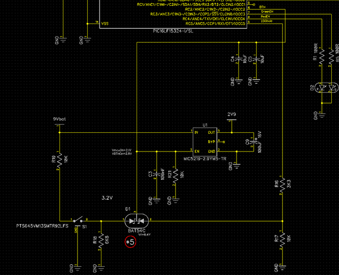
Auto Off is solved with a design called "selfhold", almost what can be done relays. The button S1 enables the LDO and the whole board is powered. It should be above 400mV on the enable pin to keep the LDO on. When the MCU is running it will output a signal to the LDO keeping it turned on for 20min. When this time has passed the IO pin LDOhold goes low and disables the whole circuit.
Also the S1 switch is used to choose between the three user modes. S1 is connected to the IO called BTN. This pin is configured as a analog input. It can then distinguish if the button is pressed or its only the voltage form the LDOhold signal that is present.
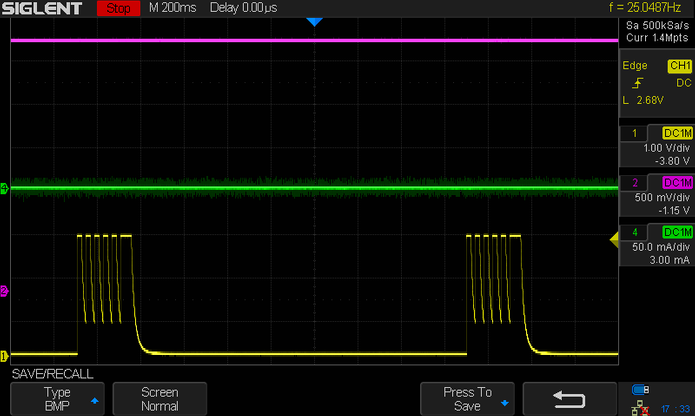
In safety mode and without any load connected the output will send the short testburt pulses with 1s delay. Of course no high power is output because wrong resistance is sensed.
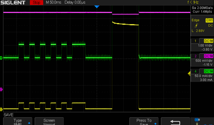
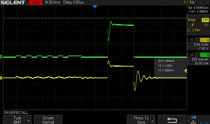
Complete safety logic can be seen in the pic above. Ch1 is Vout, Ch2 is MCU VDD, Ch4 is Iout. The circuit is loaded with e 3.3ohm resistor.
First the MCU checks if there is any voltage present, if not it will send out 5 short 20ms pulses folowed by a 50ms pulse. The resistance is checked 6 times. If the value is correct it will output the highpower pulse of 100ms.
Power supply to the MCU is actully falling slightlty when the high power output is present but it will not affect the performance since the voltage is stable when the short measuring pulses are performed!
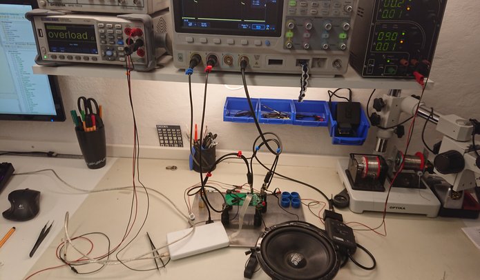
When connecting a real speaker the signals where affected by the real coil and other speaker parameters. Althought the resistance measurement works well for most type that has been tested. One issue i had was that when i thought i had a working circuit a went and showed it to a person that work with caraudio so he could test and rewiev it .When he hooked it up to some speakers severall of them didn't work and the tester showed wrong resistanse. I tested them in my lab and they worked.
The conlclusion was that the workshop where the speakers where stored was around 16degC and my lab is around 23Cdeg. The cold made the speaker cone stiff and this messed up the resistance measurement thinking the resistance was lower. This was solved by connecting a 2Ohm resistor in series with the testobject to ground to elevate the measuring voltage and to recalibrate the adc value to be compared with a higher number. Initally only one resistance pulse was sent but it's more stabele to send out six and measure it severall times.
2021-02-08 PiPower
I got a request to build a power supply for Raspberry Pi 3 B+ in the form of a Pi hat. Specification says it requires 5v and 2.5A. Althoug scroolling the web it can be found that an estimated average current load is around 1A or below.
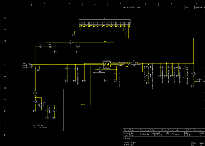
The supply will be used in automotive appliaction and needed to have a delayed 30s on and off. This is solved with a diod and a RC net on the enable pin for the regulator
I choose a swithched buck from TI, LMR33630 and it is designed for an input voltage of 13,8Vnom and 5V/3A output.
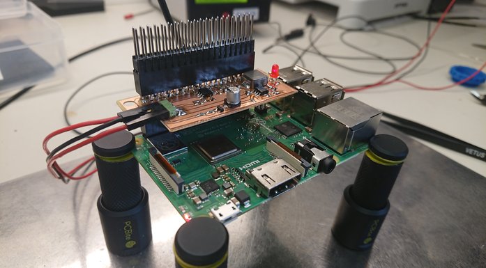
The power board is tested for output voltage, output ripple and total maximum temperature at 2,5A and 1,5A current load.
At 2,5A continuous current load the temperature will rise above normal operating temperature if the board and regulator is not cooled but at 1,5A load the design works fine without any external cooling.
In the picture below i use my newest tool. A oscilloscope probe that user doesn'tt have to hold and is attached with magnets to a plate. Its the 200MHz passive probe SP200 from SensePeek.
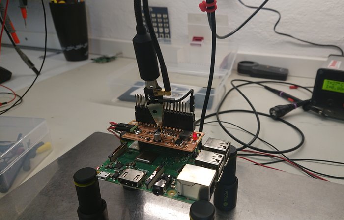
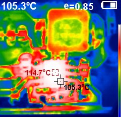
2,5A current load tests
The hottest spot is the regulator with its 114,7Cdeg.
Output ripple @ 2,5A
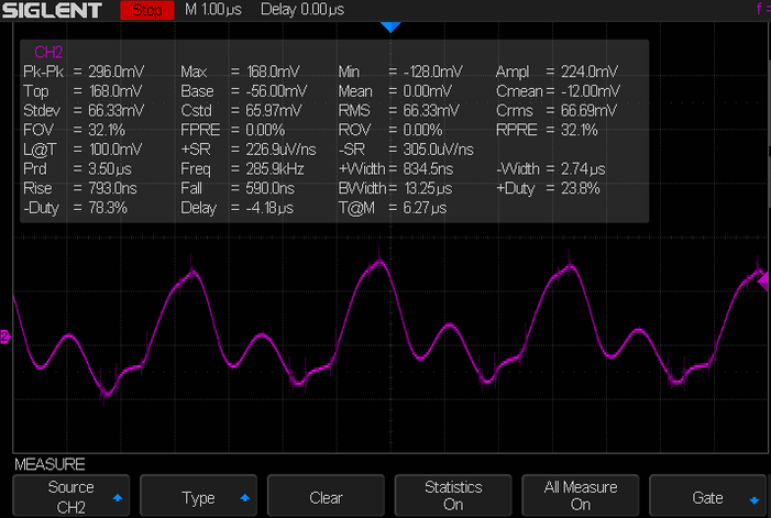
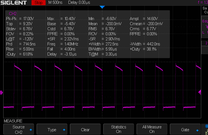
Switch node
The swithing pulse goes bad when current above 2.2A is drawn from the regulator. The reason for this was that ai actually forgot to mount the input capacitor of 10uF. Even though i have a good quality bench power supply it still neede its input capacitor to work as designed. This shows the importance of following all design rules when it comes to switched regulators. After mounting the input cap the switch was fine as shows the pic below
1,5A current load tests
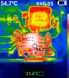
Regulator temp is 58,7Cdeg with 1,5A load which is much better
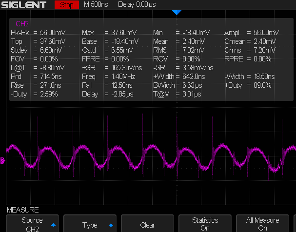
Output ripple @1,5A
Switch node
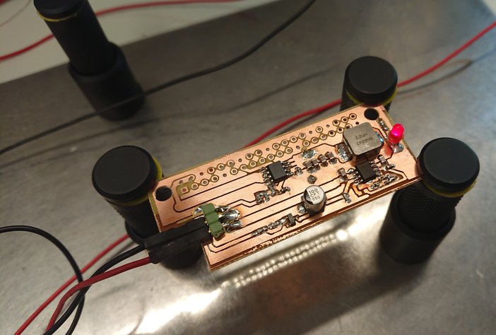
I prefer normally to order real pcb's but since i was in a hurry i etched the board in my lab. Its simple and cheap. But i cannot produce a good board reagarding thermal aspects. With a real 2 sided pcb the entire design would be cooler at high loads!
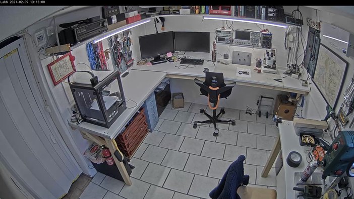
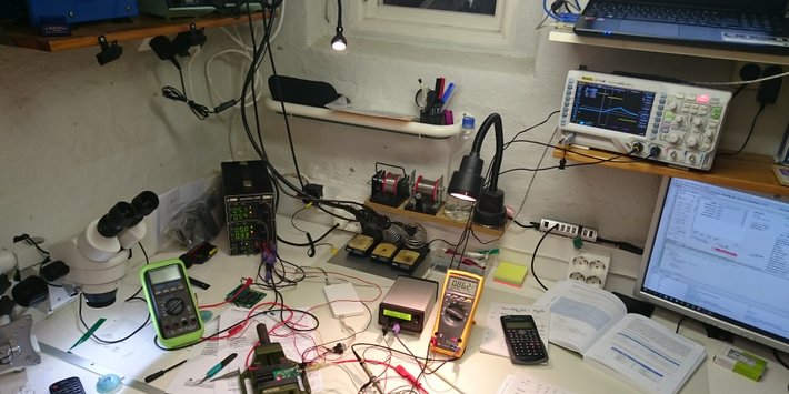
2020-12-15 New Lab
Finally the new lab is up and running. Everything has its place and the workspace is well thougth thru. Instruments are easy accessed and there is alot of space to work on!
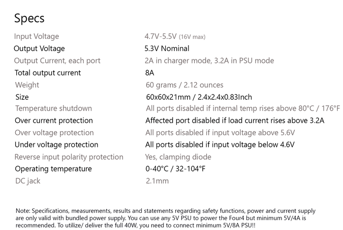
2020-06-17 Four4 usb charger
So it was time to make another kickstarter project. At first i needed a reliable charger at home due to that increasing number of gadgets we are charging. When i designed it i was so good that several collegues wanted one and they all liked it. It was then decided to make it as a crowdfunding project.
It uses the 16F18346 controller which is a cheap and feature packed mcu with alot of memory. At first i used a smaller mcu but when starting programming the memory wasn enought. The Oled display uses more than 50% of the memory due to it's drivers. Good to have in mind.
Another issue i had with this newer mcu was that i never succeeded to actually set up the registers correct to use the internal I2C modules. I ended up using software I2C. Slower but works fine in this application.
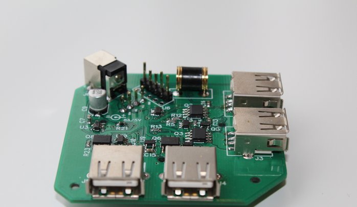
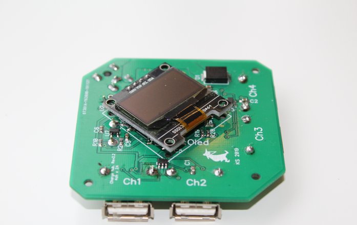
Two sided main PCB is used and both top an bottom of the casing is black FR4 material. The sides are 3d printed
I put alot of effort into the product to make it bulletproof and i have worked more than 6 months on it. Had alot of issues with the wall power supply and discussed with the vendor.
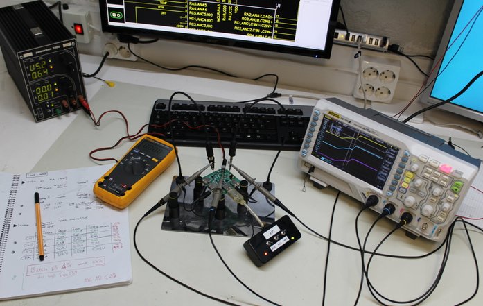
I tested and verified everything to the extent that there were no isses left!!
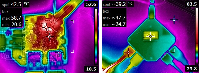
One main feature of it was thet it had almost zero internal resistance and therfore it had very low voltage drop and powerloss at maximum charging power. It had really low temperature at high load!

The campaign failed unfortunatly bigtime. I had way to high pricing on a complete kit. Since i made it initially for myself i had no thougts on making it cheap and alter on it was hard to change the design.
I learned my lesson. Always keep prices as low as possible. People will NOT pay much even if the product is perfect
2019-03-21 Car security
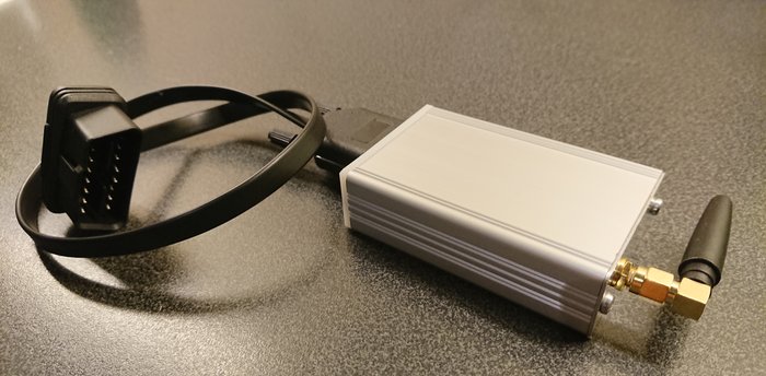
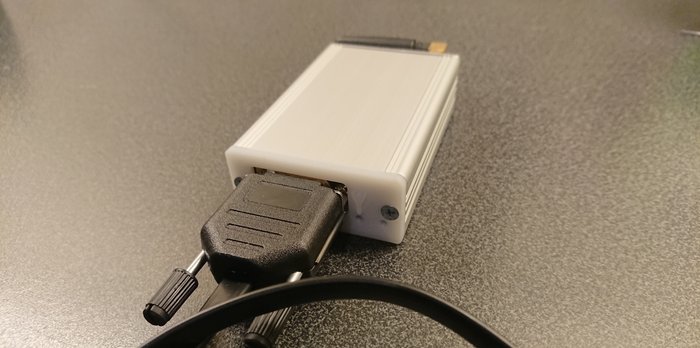
New cars are often delivered without any alarm installed. And the user does not really want to install an aftermarket because it's expensive and you probably will need to cut wires etc.
Therefore, I wanted to design a simple alarm that is very easy to install. Of course, easy to install is hard to combine with bulletproof design but with some well thought through compromises I designed an alarm that is.
-Easy to install. Connected to OBD connector, no additional connections
-Detects shock/impact to any part of the car
-Measures battery voltage to control the alarm, neg voltage transients when unlocking doors and higher voltage levels when engine started.
-GSM enabled
There are to ways to detect the battery voltage. One is by reading ADC channel 1, this is used to detect if the engine is started Vbat>14V. The alarm module is not active if engine is on. Also, low battery voltage is detected by the ADC.
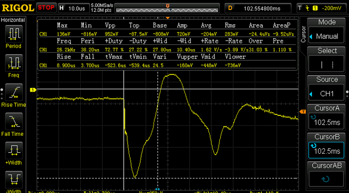
I did a lot of measurements of the battery voltage when unlocking the car and the pic above shows that the voltage level drops with 800mV when doors are unlocked. Great but this is under a very short period, 10us.
I tried to catch this with the ADC, but the ADC need around 4ms to complete a reading. The built- in comparator module was fast enough to handle this fast transient.
Every time this pulse is detected the software goes into a delay loop for 10min so driver can enter the car without triggering the alarm.
Detecting impact to the car is done by ADXL345 accelerometer. It communicates with the MCU through I2C which is used for setting up the chip but also for resetting it after it has been trigged. The ADXL345 is configured to detect a single tap, when this occurs a logic output pin goes high which is sensed by the MCU. Then a I2C reset command is sent to the ADXL345 chip.
I did a lot of sniffing the I2C bus to the accellerometer chip both to control what I'm sending to the ADXL345 chip, and what the chip responds. I also did a lot of trouble shooting when trying to identify the I2C restart issue
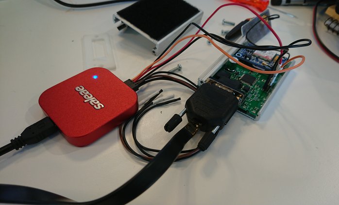
Without having a proper logic analyzer it's impossible to sort out any issues in this kind of signals. I bought a cheap eBay analazyer which did not work well at all. I decided then after Googling to try the Logic 8 analyzer from https://www.saleae.com .
It's their smallest model but it worked great instantly without any time lost trying the get it work. The biggest benefit is that it just works without any issues and on everything. The days and hours one save on using Saleae instead of some weird clone is worth every cent of their "high" purchase price.
Below is the communication between the MCU and the ADXL345 sniffed and decoded by the Logic 8. The analyzer shows also a real good picture of the signals but for this purpose the actual writings are more of interest.
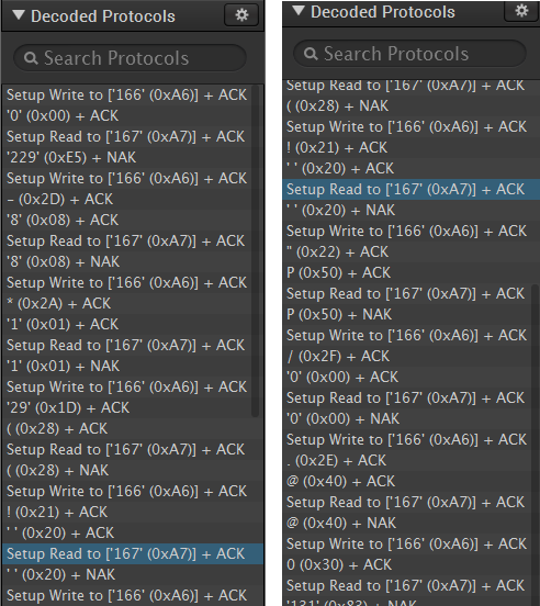
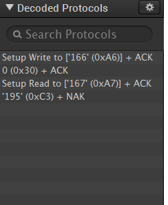
It took some time to find correct settings for the ADXL345 chip to work as desired. The commands above are sent once to the chip when the circuit is powered, and configures the chip with correct threshold levels etc. Every command is first sent and then i read the register to see that correct command is entered.
The commands to the left are the reset command and is sent every time the accelerometer needs to be reset.

Pic 16LF1937 has all modules and can be clocked up to 32MHz, which is well suited for this project. Although the code runs on 16MHz. It's required to be fast enough to catch the unlock pulse. I put a lot of effort by solving this by a interrupt trigged by the comparator but it was triggering in a way that was unpredictable, and I didn't find any solution. I dropped the interrupt idea and wrote the code to be fast enough instead. It uses a counter 0-10000, the voltage transient is checked every cycle while the ADC readings are done 1/10000. Basically, it could miss one unlock transient but it's really low risk.

Real life testing.
During development I had one big issue with the pic reset/restarted randomly. That was what I believed initially at least. After a lot of testing I found out that sometimes when the output from accelerometer was trigged and detected by the MCU, it should send the reset command through I2C, but it did sometimes reset. Originally, I used 18F4685 but due to not finding any solution to the restart problem I decided to go with 16f1937. Changing the MCU solved the problem I thought.
Built one more fully assembled unit with the 16F MCU and the restart problem was back. So, I had one unit fully working with the new MCU and unit with restart issue and new MCU. I put a lot of work into solving the issue but could not find the root cause unfortunately. First, I had enabled the i2c module in the chip and thought it woul be a good idea to try the software I2C routines instead and see if that would make any difference, but it didn't.
I got a lot of help from forums on what I could test, but nothing pointed to any root cause and no solution was found. At the end my conclusion was that it might be some timing error that occurs sometimes when the I2C reset command is sent and that will hang the entire routine which will result in main program not executing.
Finally, I wrote some additional code that kept track if reset had occurred or not and then force the whole program into "normal" behavior. Sad to not find the real cause but I felt that I had tried everything. The alarm works well but the code fix is not the best solution!
Since then I have used I2C in several much more demanding projects without any issues more that writing correct commands to correct registers.
Two working units are mounted in a Mercedes C class and one in an old Opel Vectra. The alarm module works perfect in the Opel but in the Mercedes, it is very hard to trigger the alarm. The Mercedes is a much more stable car and trying to shake it will not trigger the accelerometer, maybe if something crashes into it or somebody takes a big rock and throws at the car it will trigger but that's kind of hard to test :)
In future I might make a new version of the alarm equipped with a mechanical shock sensor such as the 801S instead of the ADXL345 and that way make it more sensitive (and cheaper).
DIY Watchwinder 2018-08-22
Automatical and mechanical watches have power reserve of 30-50h. Leaving them unused for more than that will make the watch stop, and you have to wind it and set time and date. A watchwinder can be used to keep "power reserve spring" winded for a longer time.
It's not recomended to leave a watch on winder for months because the spring needs to rest if the watch is unused. But it's perfect when the watch is laying still for a weekend or so!
When building a winder it's a good idea to have as few RPM's as possible, just to keep the watch winded but not more!
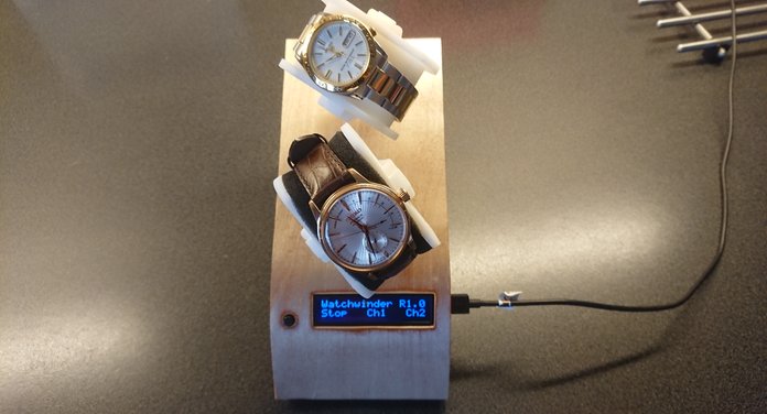
Fortunatly i have a power reserve meter on my Seiko watch where it shows how winded the watch is measured in hours. I will use this feature to really set proper RPM and not overwind the watches, of course with some added marginal. At the moment it keeps the watches winded but i don't know how much.
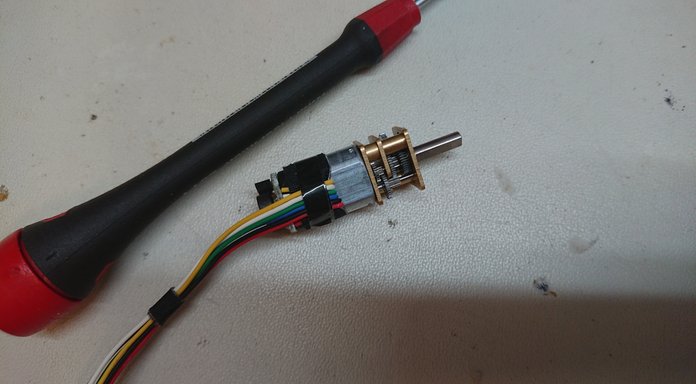
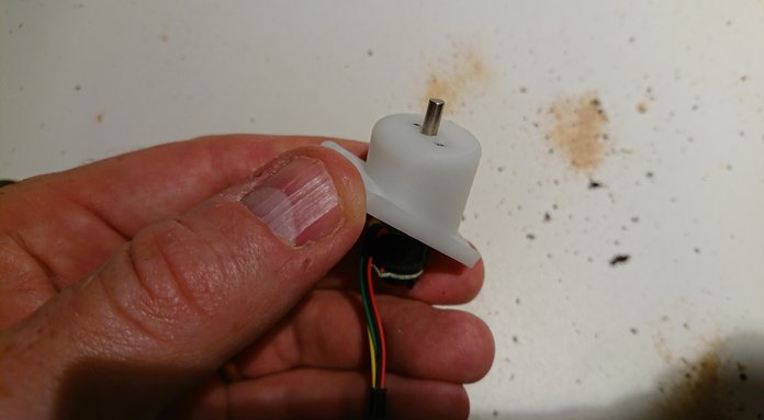
I decided to etch the PCB, so the esthethic result is not that great but it works well. The program is simple and can be downloaded for the 16F1847 mcu used for this project. I use two SMD H bridges which can be powered with 2.2V-6V so they will be able to power almost all small motors used. They H bridges are supplied by an adjusatble regulator to set preferred voltage by a voltage divider.
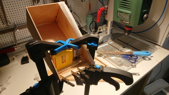
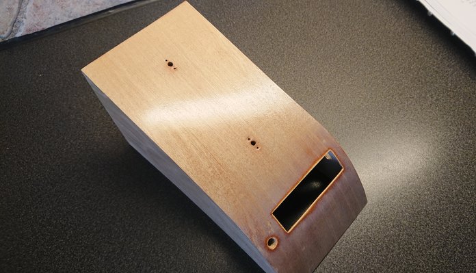
The housing is built of 0.6mm plywood as the cower is bent and 2mm plywood for the sides and bottom.
Also some 4mm balsa was glued to reinforce the bent plywood after it was glued together.
Unfortunatly the casing acts like a guitar and the otherwise really quite geared motors where loud enough to disturb when mounted in the casing. I damped the wood case with asphalt sheets and lowered the motor speed as musch as possible. It helped alot but i never got really satisfied with the noise levels.

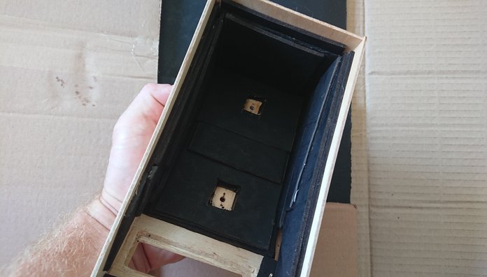
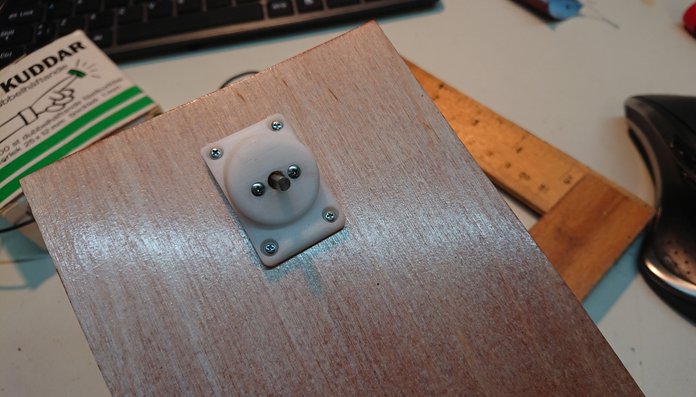
First the motor was mounted into the case and i was relying that the tilt of the top was enough to rotate the winder weigth but i needed to add more angle to move the weight. Therefore i 3D printed a small extra console for the motors with greater angle.
The mechanical assembly is 3D printed and both looks and works great. I had to reprint a couple
parts due to the fact that printed parts shrink and holes become to small. Adding 10% on hole dimensions and so will make the real printed part fit perfectly. So a thumbrule is 10% shrinkage.
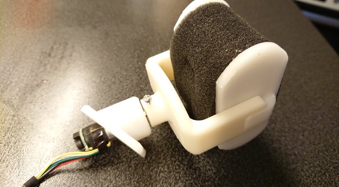
One watch "pillow" is for smaller watches and the other one has added foam to increase the diameter for bigger watches.
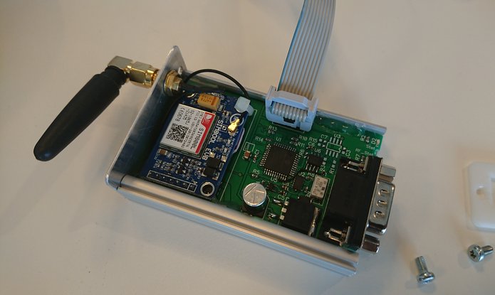
GSM IO module 2018-05-21
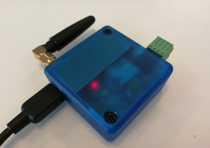
Designing a universal module with one 12V input, one 5V IO that can be configured as ADC input and one output that can deliver +5V/~300mA to control external circuits such as relays. I also wanted to use a of the shelf box.
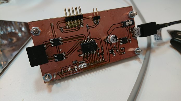
Made a tight power desing with a internal 3A LDO which is intended to be powered from a 5Vusb power supply. Also tried to have a small form factor and use the Hammond 1551RBT enclosure.
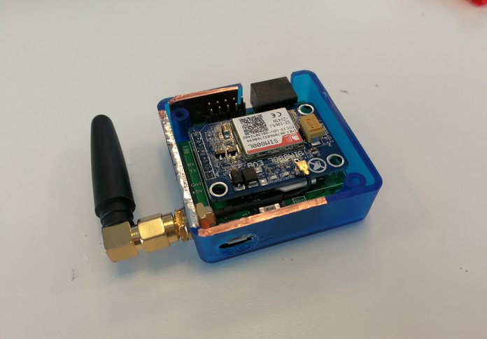
As few components as possible were used and PIC12F1840 is used as mcu.
Second time i use the SIM800L module. After this project i can fairly admitt i was lucky with my first project having no issues with the module.
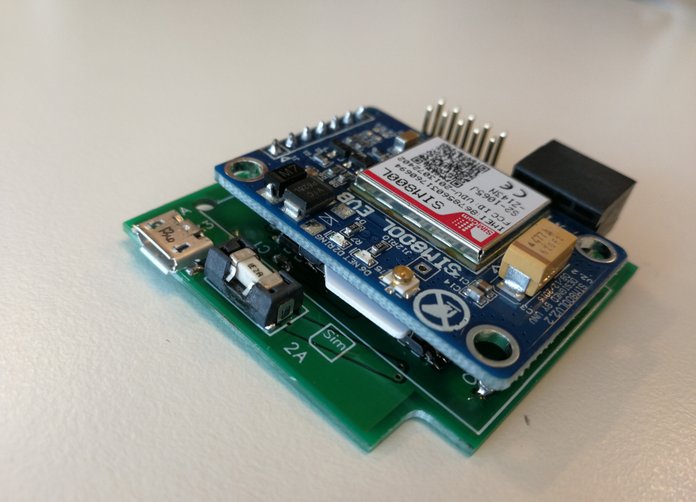
First of all this module can require up to 2A current supply in worst case, this is mainly for short periods but will display if your power design have any flaws. In my previous project i was lucky using a big 7805 reugualtor powered from 9Vdc.
With the tight power design i thought it would be enough to supply the module with 5V and have internal system voltage on 4.6V. It did not work, the Sim800 module did not get enough power when connecting to the GSM net. The solution was to increase the internal voltage to 4.84V and to find an USB charger with higher output voltage than 5V. The Apple 12W charger is the far best alternative for this module. It outputs 5.2V and 2.4A.
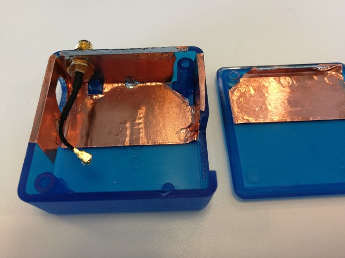
Finally there were alot of issues with antenna placement. This module is physichally small and the antenna is close to the electronics. Often the antenna disturbs the GSM module making it lose GSM net and resetting itself.
After many attempts the final solution was to add some copper tape connected to ground as shielding between antenna and module!
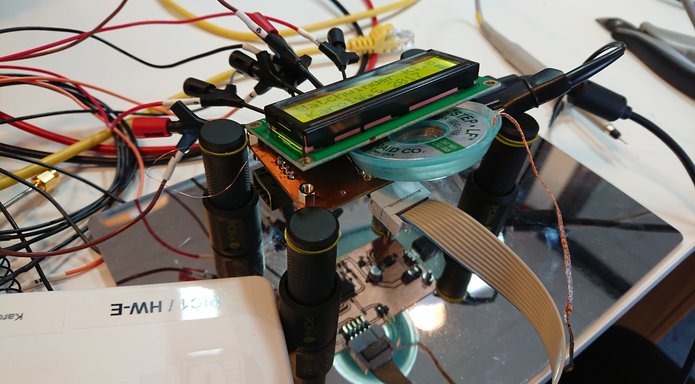
GSM update 2017-12-06
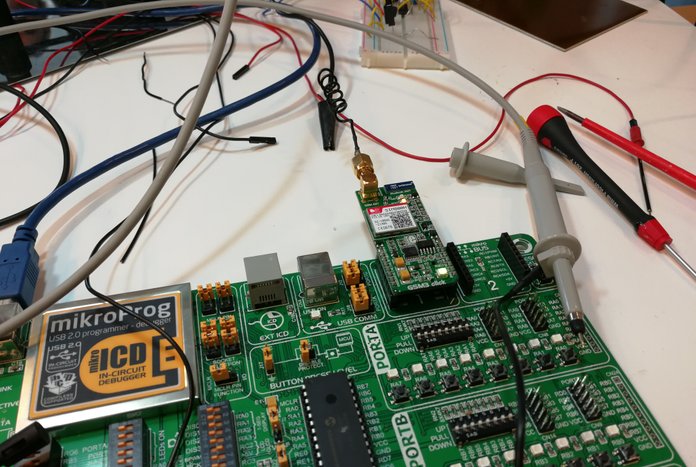
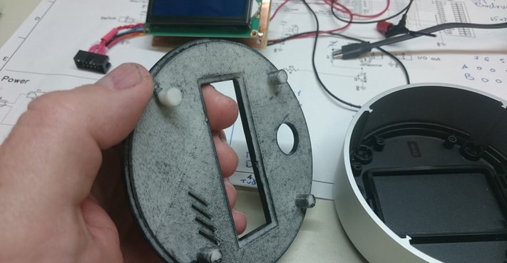
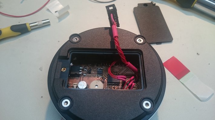
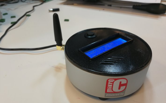
Why not make the Home Diagnostic system below even better with extended connectivity thru GSM!
Tested some simple code with EasyPIC7 dev board and the GSM click 3 from Mikroe to see how it can be done. The GSM click 3 is expensive and not well suited for more than prototyping. Fortunatly its possible to buy the SIM800L gsm module for around 8USD on ebay and they both use the almost same GSM modem unit. Same code and ATC commands can be applied on both.
Connected the TX pin of the SIM800 module to the UART input for the PIC. Powered it by 5V.
The code is written in that way if a wireless trigger detects a event/incident it will send one SMS to a pre set mobile number and inform the user which sensor has trigged. Not all events will trigger the SMS function. Recieved mail is one that will not trigger SMS function.
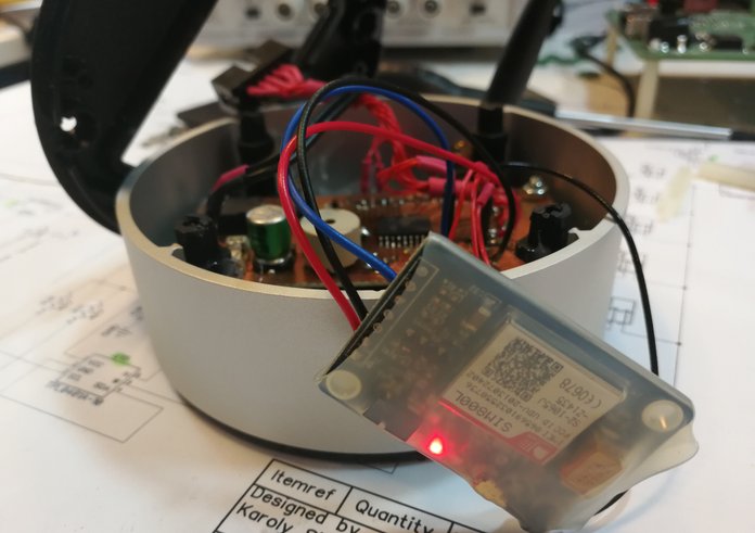
Crowded inside!
Home diagnostics 2017-08-23
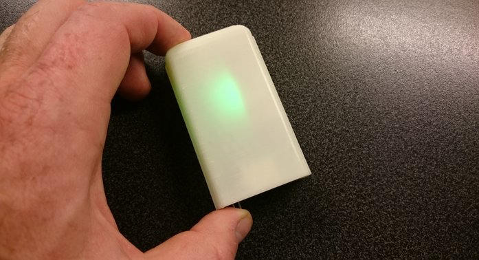
Some time ago i realized that i wanted to have some kind of system monitoring water leakage, mailbox, cooler and other important things in my home. One reciever with a display and sound that recieves data/ triggering from several wireless 433MHz sensors. Things that will be monitored are
-Cooler
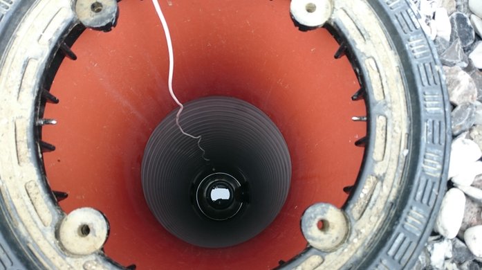
-Drainage wells (2pcs)
-Mailbox
-Garagedoor
-Waterleakage5pcs
It will also be easy to add new sensors to the system in the future by updating software.
For data transmission a couple different 433MHz transcievers has been tested where the best had very good reach and fucntions but where to expensive. Sine i will monitor many nodes the price of each sensor card i important.
The HC-11 transciever can found on ebay for 2,5Usd and has a reach of 15m indoors with the bundled spiral antenna. Better antenn will improve transmission reach. I have done alot of testing with HC-11 and have not found any cons so far. I'm using default settings for the modules but they can be set by user. Only gnd, Vcc and data pins are used. One thing i noticed that different batches of the HC-11 loads the power rail uneven. I needed to increase the bulk capacitors to 30uF close to the Pic, othervise the Pic was resetted every time it attempted to transmitt data.
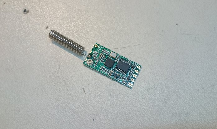
TX-unit
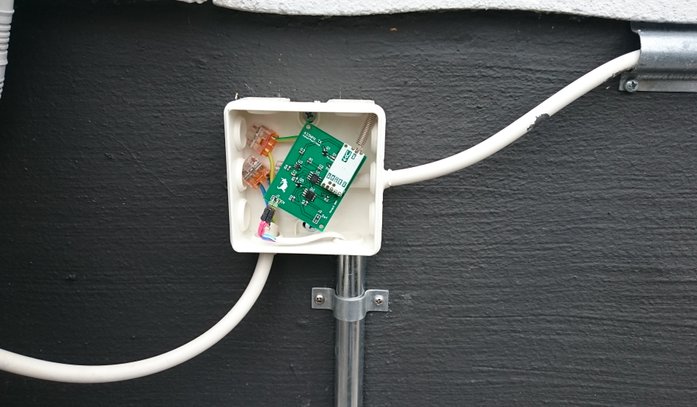
The TX units which i call sensors can be used in three ways. The sensor board can be completly off when used in water leackage monitoring and is actived by shorting two probe pins with water. These pins controll the enable pin on a small SOIC LDO. Two CR2032 batteries will provide power for many years.
For the mailbox detection a IO pin is connected to a micro swithc close to the hatch. The sensor board is now always on and draws 800uA in idle mode. Transmission is during short periods and current consumption will be 30mA. In this case a small rechargeable battery with solarpanel is used.
It's also possible to read analog values but this function is not implemented in software at the moment, only supported by the sensor board.
Since many sensor board will be used i ahve tried to keep down the cost to around 5Usd/pcs. This includes
2 CR2032 batteries with holders
1 HC-11 RF unit
1 PCB
1 NMTS4177 fet used as load switch
2 BC847
1 LP2985-5.0 LDO
1 Green SMD LED
and some RC components and header connector pins
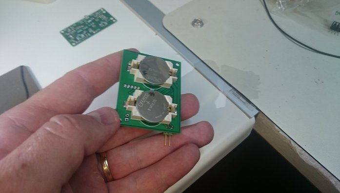
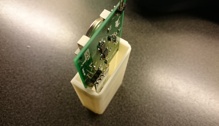
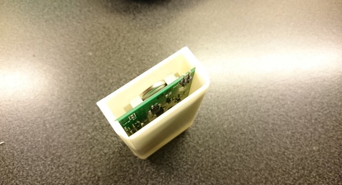
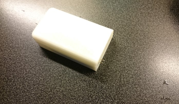
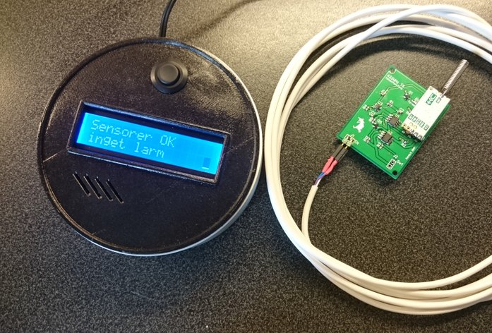
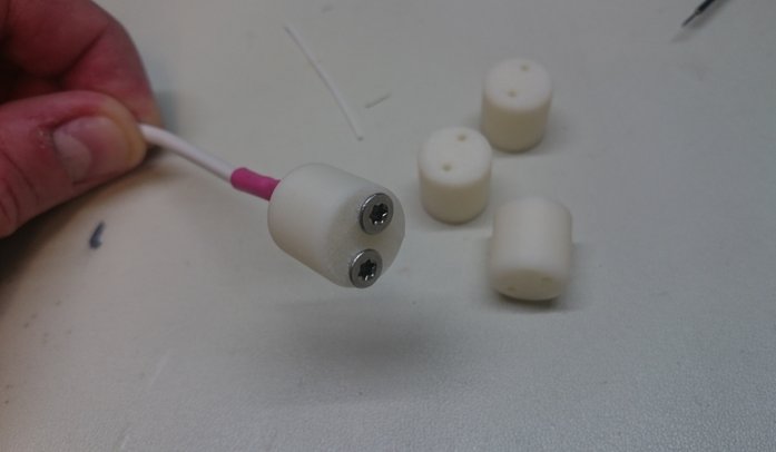
The first unit is used as water level indicator in a drainage well. For this purpose i 3D printed a small round holder to connect the sensor wire to which then are held in place by two small screws. These screws will actually sense the water level.

RX-unit
The RX unit uses the same RF module and outputs information on the 2x16 display, in some cases a buzzer is enabled. Since more sensors will be added in the future i have chosen a PIC with as much flash memory (14kB) as possible. 16F1846 has alot of functions and the main feature i use is of course the built in EUSART module.
The way the whole system work is that every sensor sends a unique word depending on where its mounted. The sensor in the well sends the word "Well" and when this is detected by the RX unit, it will alarm and tell the user which sensor has trigged. To save battery life the word is sent 10 times. After transmission is complete the RF module is disabled.
A load switch will output 12Vdc from the RX unit which can be used to trigger external IOs. It can of course also send information to other external units but this is not implemented for now.
2016-11-16 UsbSafe²
Making a second attempt on my USB fuse, but this time with SUCCESS!!
Added some requested functions and the fuse features now
1Current limit/monitor mode.
2Over voltage protection. (6.5V)
3Anti Juice jacking mode.
4Higher max input voltage (15V)
5Better pcb layout & design.
Follow the link to CrowdSupply and UsbSafe²
Dave on EEVblog finds a UsbSafe² in the mailbag!
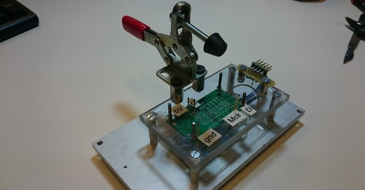
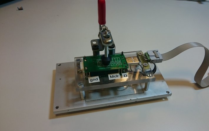
Producing 100 units of UsbSafe² requires a jig for production flashing. I use the unpopulated pcb for UsbSafe² with drilled hole at every test point. Pogo pins are mounted in the holes to apply connection to the boards to flash. The pogo pins are connected to the flasher thru a 10pin header.
Crowdfunding summary.
The first thought after having a succesfull campaign is that it's really really really hard to have any real economic success. There is alot of expenses that are really hard to predict. There are alot of small amounts of fees that in the end makes the profit become zero in best case.
Production costs will always be higher than predicted. Import taxes has huge impact on profit and can easily be forgotten. Dave on eevblog has a recomendation to at least sell your gadgets 2.5*cogs to cover all expenses. I had around 2.0*cogs and it was not enough. My profit was none. I barely covered production and shipping expenses!
With that said, i did not loose any money and it has been great fun and experience to follow it through. I learned alot and will not fall into the same traps again.
My main lessons from this campaign are
1 It's great fun and i will do it again!
2 If i cannot set a price=2.5*cogs or more, i will not go through with the idea!

Update 2017-03
1st batch of units are ready to be delivered. Itead produced 100pcs. They all look great. Only 4 units didn't work att first. Three had excessive solderpaste which short circuited a transistor. One unit had a faulty transistor that was replaced. Except this they all worked out great.
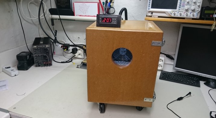
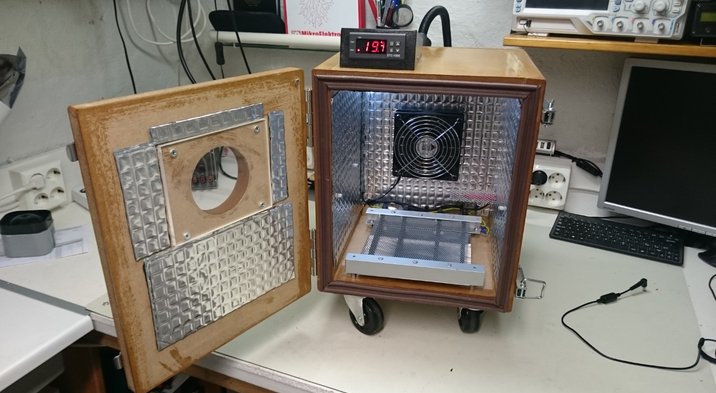
2016-10-10 Heat Chamber
I needed a heat chamber for testing different designs. Having some time over i built a 20L heat chamber in the easiest way. The box is built with 25mm mdf. Using a really cheap STC-1000 temperature controller gives enough accuracy (+-3 degC).
As heater elements two 250W/230V heaters are connected in series to calm the whole system down and not make the temperature variations to fast. Maximum temperature for the chamber is 70degC and takes about 20min to reach. Also a LED lamp for 12V is installed for better vision.
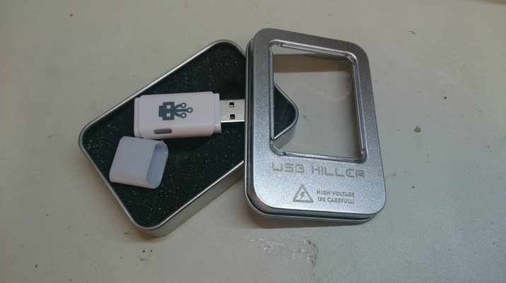
USB killer V3 2017-05-12
When i was running the Usbsafe crowdfunding campaign i often got the question if my fuse was designed to protect against Usb killer. At that time i didn't even heard about this device.
Since then i seen alot of videos of what this device can do/destroy, so i decided to purchase one myself and see what it does.
Specifications below is from the Usbkiller homepage
Killer Specifications:
-Input voltage: 4.5 - 5.5 VDC
-Output voltage: -215 VDC
-Pulse Frequency: 8 - 12 times / second
-Pulse current: ≥180A
-CE & FCC Approved, allowing you to test in complete safety.
From this i could theoretically thatt the output power should be P=UxI=215x180=38,7kW.
Of course this is not possible in reality. The high voltage is possible to achieve but not at the same time as that kind of current output.
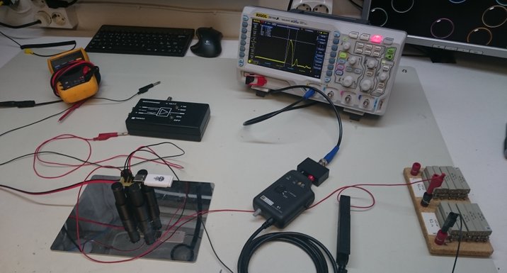
By loading the killer with 100 ohms a more realistic measurement can be done. Unfortunatly the results are terrible to see. The killer is really "well" designed, It ouputs high energy very very fast! Results below says it will be pretty hard to build something that can protect the Usb port.
Falltime=260ns
Risetime=4.8us
Pulsewidth=16,7us
Amplitude=226Vpp
Amplitude inc undershoot=348Vpp
Calculated power > 510Wpeak
There are not many alternatives to design a good protection device for this mad gadget!
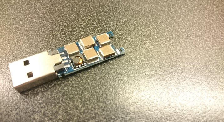
Basically usb killer is a DCDC voltage boost which takes 5V from the USB power outlet. The killer boosts 5V to around 200V and send it back into the host thru the datalines. Also it can be noted that the voltage sent into the host has negative polarity. Most likely to be able to pass any kind of over voltage protection.
The killer generates high voltage as long as it's powered from Vbus!
Loading the output even harder with only 4ohms which can be considered as a shortcircuit reveals interesting output characteristics. The highest current output is around 6-7A and the voltage is almost 22V. This will result in a peak power at 154W.
When loading the killers output with 16ohm it can be seenn that the first burst pulse is highest and then it declines with time. Channel 1 is voltage and channel 2 is the current
A closer look shows that the real energy can be be found within the -157V but the total amplitude p-p is around -200V. The fequency of the high voltage output is 1kHz and the duration of the negative pulse is 260us
Due to the amount of energy the killer produces and the time the pulse is present compared to regular ESD discharges it will destroy most standard ESD protection solutions. It's only a question how long it takes.
Putting really big TVS diodes on the datalines that can withstand the killer is not possible. They have to high capacitance and will therefore make real datatconnection impossible.
I will try to analyze the output from the killer and see if it's possible to build any kind of protection against it and at the same time at least have Usb2.0 datatransfer rate possible.
I use differetial high voltage probes to not damage my oscilloscope and a 10A current
clamp to analyze the waveforms.
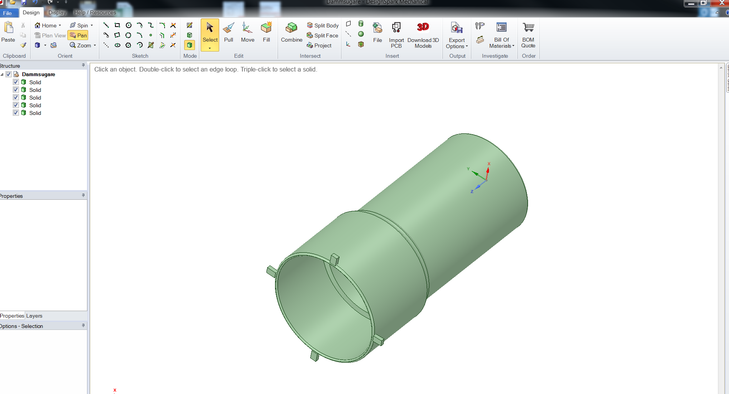
2017-03-17 3D printing
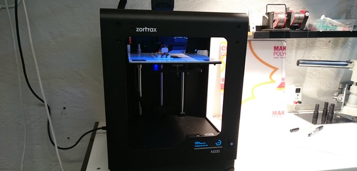
One thing i have always lacked is the possibility to build custom made enclosures and other smaller mechanical solutions. The 3D printing has been around for a while but i have not found any printers cheap enough and with really high quality prints. Also i'm not amused by having calibrating and tweaking the printer to get sufficient quality. So the need for a plug n' play printer was a must.
By coincidence a collegue had a plug n' play printer he was very happy with and he showed me some printed samples that looked great.
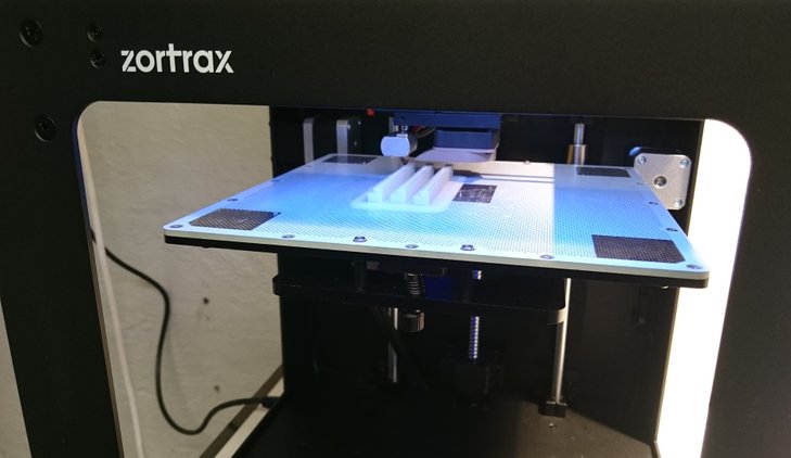
The Zortrax M200 from 3Dprima has exactly all i wan't. U have to use their own filament which is a bit more expensive but every print turns out great without any tweaking.
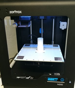
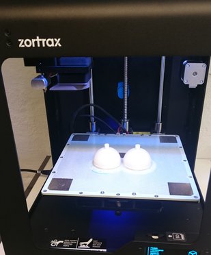
I'm not used to design with mechanical cad tools at all but the one i'm trying to learn is the one from Designspark. Below you can see some really simple design i've made just to get started both with the cad program and the printer!
2017-02-08 Signal Hound Spectrum analyzer
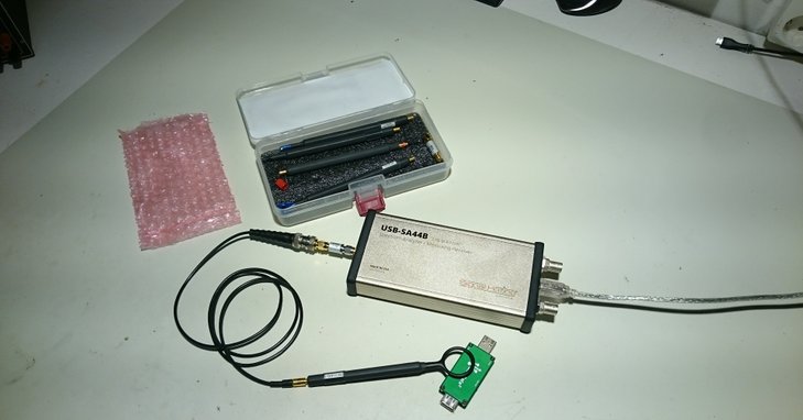
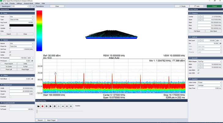
Since i'm trying to learn more about RF emission and EMC, i purchased a spectrum analyzer. Its hard to find one that a hobbyist can afford, but i stumbled upon the SignalHound which is a "affordable"
spectrumanalyzer that can measure frequencies DC-4.4Ghz. They have also a bigger unit that can be used for pre compliance testing.
For some reason it cannot handle DC voltage on the input so a DC block i highly recommended. Except this it's a great device with a lot of magic and usablitiy togehter with great software and hardware!
In Europe you can get it from the official dealer Foltronics in Holland.
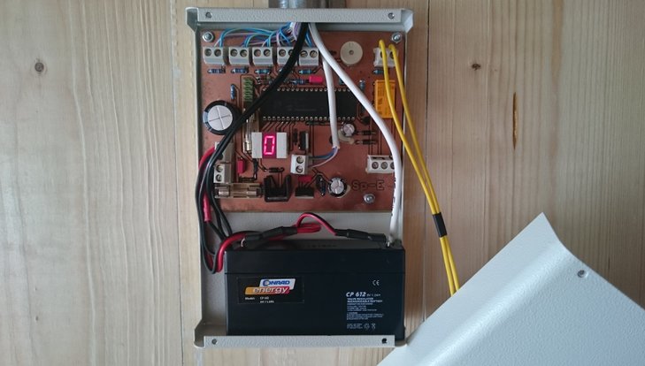
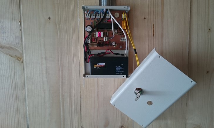
2015-06-01 Security System
A friend rebuilt his existing carport to a fully closed garage. Of course he needed to secure it with proper security system that has both theft and fire surveillance. Also i connected this system to his already home surveillance system so that it vill be connected to a security company.
The main features are:
-Two separated NTC sensors mounted in the ceiling above each car for fire detection. Also there is a internal NTC that monitors the temperature of the alarm system itself.
If fire is detected it will activate main home security system by wire. If internal heat is detected there will be an audible tone from built in buzzer.
-Built in backup battery.
-Mains power is monitored and if it's disabled there will be an audible tone from built in buzzer.
-Different logical dependencies to determine if there is doors are forced open or it's a legal entry.
-7seg display for showing status.
-Output for external siren.
-Keylock for enable/disable.
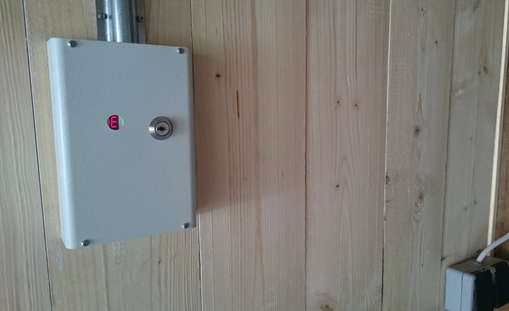

NTC sensor used for fire detection mounted on ceiling. If temperature is above 55degC it will be considered as fire by the system

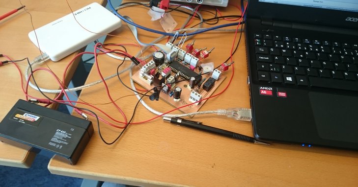
Setting timing and delays in the code was easiest to do with the real door hooked up to the PCB.

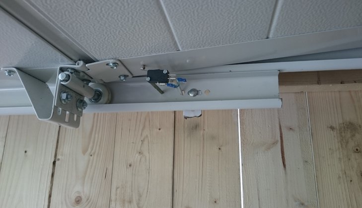
Micro switches determines if the garage door is fully open or closed
2016-02-08 Kickstarter
I wanted to try Kickstarter just for fun and the USB fuse was the thing to try.
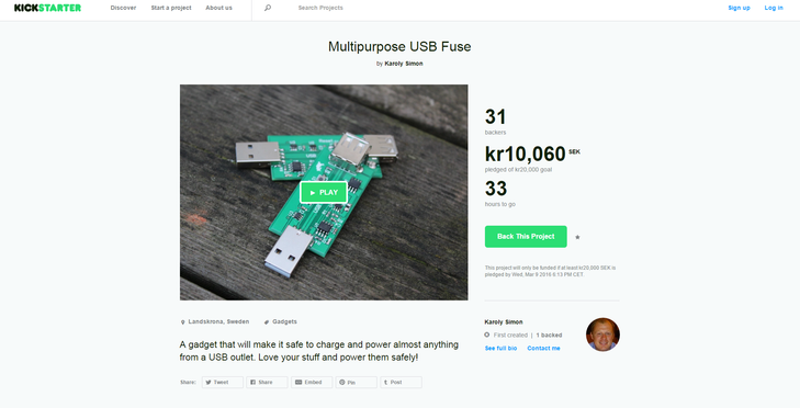
2016-01-15 USB Fuse
I often connect wierd stuff to my USB ports on the computer and the risk is that the port is somehow damaged. Off course depending on the PC the USB port is protected in different ways but it feels better to have an external fuse. At the same time i thought it could be good too have this fuse functionality when charging phones, tablets or whatever. With the growing market of endless USB connectivity it's a good ensurance with the external fuse.
There are 5 current thresholds that can be set by pressing a button. This makes the fuse circuit universal and easy to use. Currents that can be set are 500mA (USB1/2),
900mA (USB3), 1.5A (Android charging), 2.1A (Android charging) and 2.4A (Apple charging).
Each set current mode is shown if a short button press is applied. The LED will then blink fast
1-5 depending on current mode. Otherwise the LED blink every 3rd sec.
When a short circuit/ overload is detected the +5V output is disabled and the LED is turned on, the fuse is kept in this state until the button is pressed. At insertion of the fuse to a port it always shows once what current mode is set.
Maximum voltage drop across the whole fuse is around 240mV@2.4A
2015-10-01 801S Vibration sensor
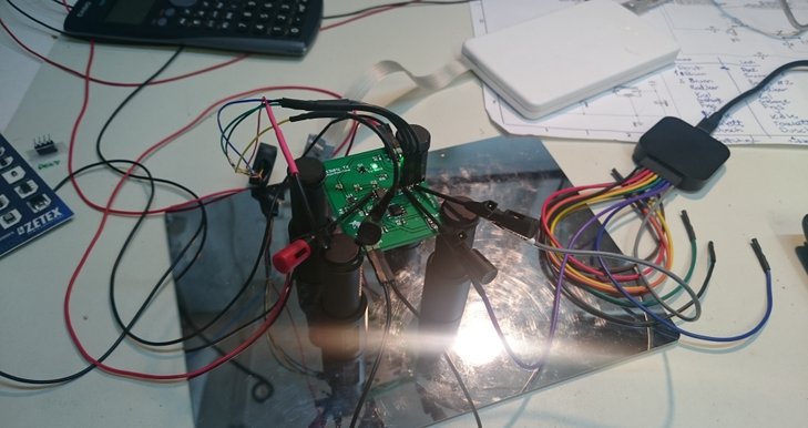
I was asked to design a simple vibration sensor module for a vehicle. The module was intended to trig a gps tracker. The tracker has built in functions for this but the function is only enabled when the tracker is in normal mode. The current consumption of the tracker in normal mode is specified to ~65mA which is alot if the vehicle is not used every day. In standby mode the tracker consumes only a few mA and can be trigged/enabled by pulling an IO high. And here is where the 801S sensor module comes in.
It basically detects a shock or vibration and enables the tracker. It uses as mentioned the 801S sensor with the recomended application circuit. For the logical "intelligence" i used a PIC12F675 which monitors if for example ignition is ON/OFF. There is to mention also a "leave time" of around 5min when the vehicle is turned of, the sensor module cannot trigger before this time has elapsed.
The only cons with this module is if the vehicle is lets say on a boat it will trig the tracker, This is solved by only having maximum two trigger events possible. To reset the module and get two new events the vehicles ignition must be toggled once.
By this solution the module and tracker together consumes around ~11mA.
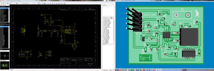
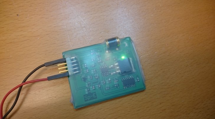
With this project i tried out how it works to send gerber files to a PCB manufacturer and get a real PCB's done profesionally.
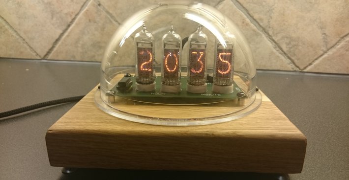
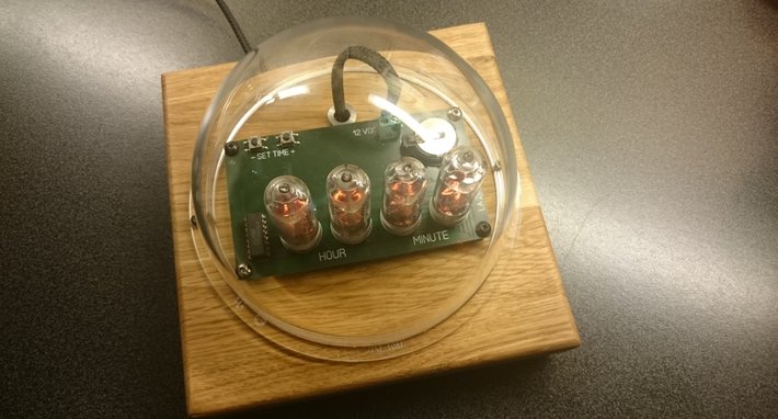
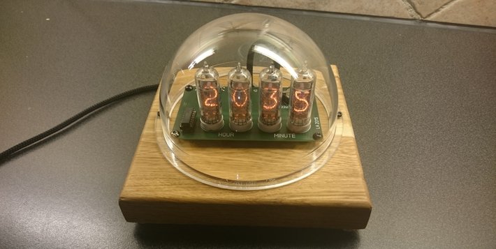
Nixie tube clock 2016-12-15
I will not write alot regarding the electronics since it's not my design. I saw a collegue build this clock and asked if he had a kit i could buy from him. The clock uses russian tubes called IN14 and they have CCCP printed on the back. Also the clock uses a RTC in case of powerloss which is great.
Using a piece of 25mm oak tree gives a nice finnish together with the protective dome which is actually a dome from a surveillance camera. It's a great looking project and i'm really happy with it. Also a cool thing which is not visible on the pictures is that the dome is treated with som kind of UV treatment. This UV treatment makes the gas in the tubes more visible and the tubes glow in even better in dark.
2014-12-23 3A Dummyload
I needed a dummyload for different testing in my lab so i started to google for a suiteable design to start from. I found the one from EEVBLOG #102 to fit perfectly.
The power circuit is basically identical to the EEVBLOG's but i added aditional functions with the help of Pic 16F1847.
The dummyload can handle 3A/ 40V/ 50W. I have tested it with 40W continuous without any issues. Above 40W the heatsink and fan cannot cool the FET enough and it will be overheated after a while. With bigger fan and heatsink this can be avoided. The Pic measures the surface temperature on the FET. Above 45degC the fan will start, and above 85degC the DUT will be disabled to ensure that the dummyyload will not be overheated.
Also there is warning when over voltage/ current/ power occurs.
Not everyday i need to use almost all of my lab equipment. Even the homemade dummyload was used to simulate different load currents.

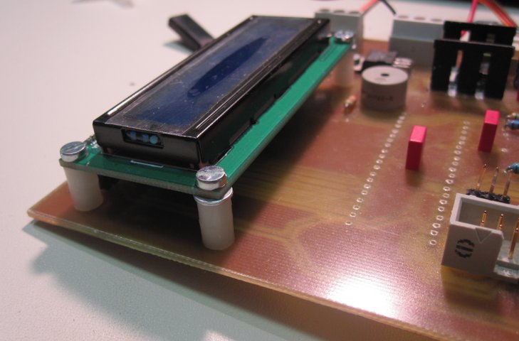
2014-07-01 Control panel
I needed a control panel for my heater system in my house. The main feature was to be able to set the temperauter from the panel instead of going down to the basement to set it. Also i wanted to be able to see the ambient room temp. I also added battery backup solution for the room panel.
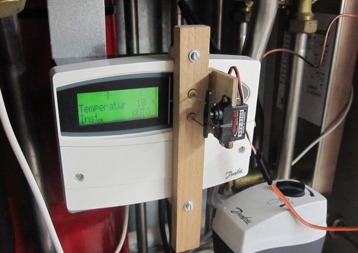
The Danfoss regulator in the heater has a communiaction bus similar to RS485 but Danfoss has altered to fit their application. My first idea was to hack into this bus but i soon realized that it would be to much work since they used a non standard protocoll.
I therefore decided to use a model airplane servo to mechanically push the buttons on the Danfoss regulator.
Below is the panel mounted in the hallway fully operational.

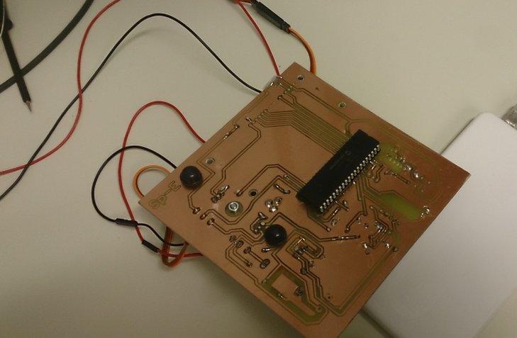
The chosen PIC for this project was 16F1973. There is a overcurrent protection circuit to the servo. If the servo consumes to high current the panel goes into protection mode and the shuts everything of. Then a master reset is needed.
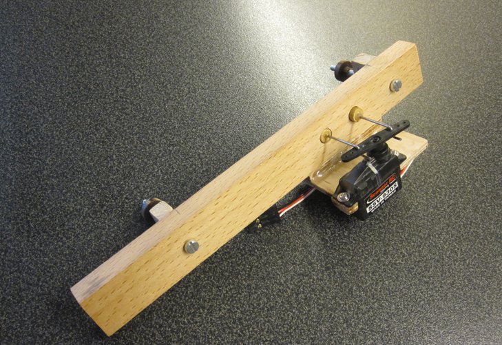
Mechanical solution of the button pusher
2013-12-09 Paintball marker
Since it's not possible to do martial arts for me any more due to different knee injuries i needed to find a new hobby. It became paintball.I own a marker which is of semi pro quality. Often when i play i want to know if i have few bullits left.
So i built a small levelsensor consisting of a LDO TPS77025 from TI which has 2.5V output, and a Pic12F675 (of course). The circuit is powered by a CR2032 battery. The way of detecting few balls is easy. I use a phototransistor FPT100, that detects light. If there are balls the phototransistor is covered and no light reaches the lens.
The unusual for this project is that it's SMD and the PIC is powered only by 2.5V which is within the specification for the PIC. Also the LDO is a low power variant.A great solution i believe!
There are three "blink modes" to understand the function.
1- LED short blink every tenth second: normal mode, more than appx 30 bullits in mag2- LED short blink 2Hz: warning mode, less then 30 bullits in mag3- LED on: low battery
Flashing the PIC circuit onboard the small PCB.

The complete marker with mag and level sensor mounted.
Using the logger Wellerman PCS100 to determine battery life time.This time is only measured for normal mode as mentioned above.
The goal was to have at least of 20h battery life time. After 91h the logger crashed and logging stopped. at this time battery voltage was around 2,74V and i consider the battery drained at 2.54V. With this i believe the total lifetime to be around 110-130h. Well above the prediction!
2013-04-07 Remote controlled hatch opener
I have a hatch up to the attic that i wanted to design a remote controlled opener for. The project below is the second and now fully working version. The first version hade major issues with false triggering when i turned on different lamps in the house and not only triggering on the remote controll.
Click below to see how it works!!!
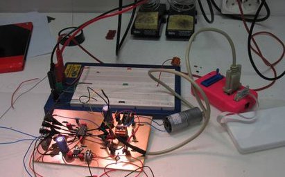
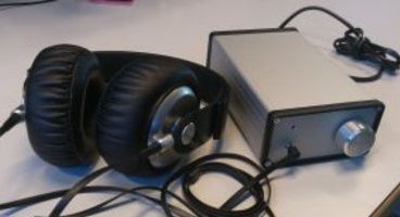
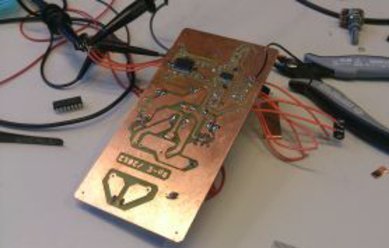
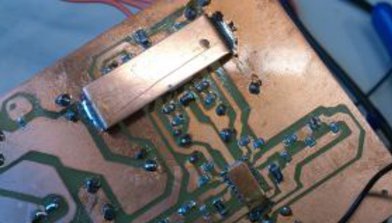
2012-10-12 TPA6120 Hifi headphone amplifier
The objective was to build a hifi headphone amplifier for myself and to CAD a pcb using SMD components.

The choice for headphone driver circuit fell on the very popular circuit TPA6120 from TI. This is more or less a OP designed for Hifi. A input buffer stage is needed for the driver and for this LME49740 (also Hifi) was chosen.
The power supply is a double 12Vdc with rated current around 400mA.In the design there are some additional filters and capacitors for reducing noise.Both OP stages are configured with gain=1, for better schematics picture pls email me.
2012-02-20 Fuel Gard.
Is a extension module to be used together with any alarm system on the market that has external input possibility.
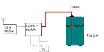
The module monitors the level in a tank to avoid theft, for instance diesel. If the fluid level decreases in the tank the module will send an enable signal to the alarm.
Most preferable is to use the module together with a silent GSM alarm that will notify that theft is ongoing.
The module has proven to stop ongoing theft . It uses aWEMA S3 level sensor or any other sensor with the same specifications.
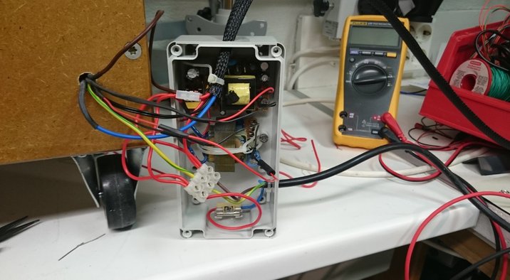
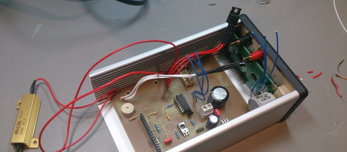
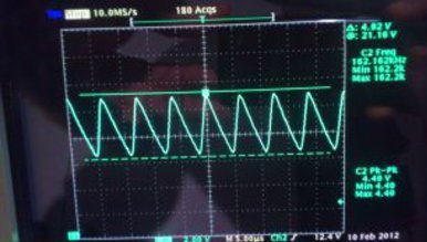
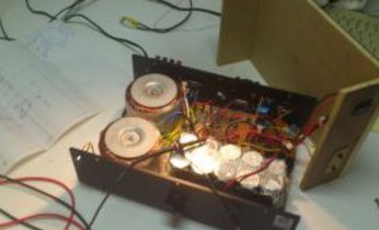
2012-01-20--Powerbox 3000 repair
I recieved an older Powerbox 3000 that wasn't working well. When i loaded the output with the maximum allowed current (2A), it had a terrible voltage ripple. The picture below show the actual output ripple was around 5V.
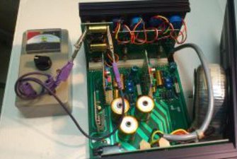
Opening the case revealed that all of the electrolytic capacitors were really old and probably dry. Using my homemade ESR meter showed that basically all capacitors were bad with ESR values at almost 10ohm.It should be 1-2ohms for a standard "low quality" cap!
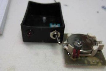
2011-09-17--Homemade watchwinder
My father owns an old automatic watch from the 1960's that he often uses. If the watch is not used for more than one day it stops and needs to be set again. I built this watchwinder for him so the watch always runs as it should.
It's based on a PIC12f675 and a simple H-bridge made by old BD139/140 transistors to reverse motor polarity. The PIC is probably overkill for this project but they are so cheap and easy to use.
The box is built of plywood which has been coloured brown and then clear coated for the "right" finish. For test purpose i use my cheap Casio G shock watch.

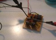
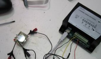
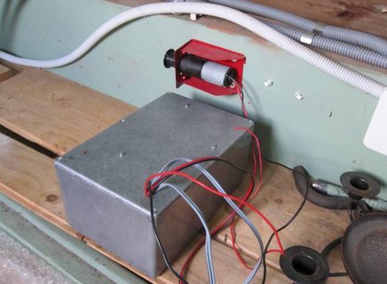
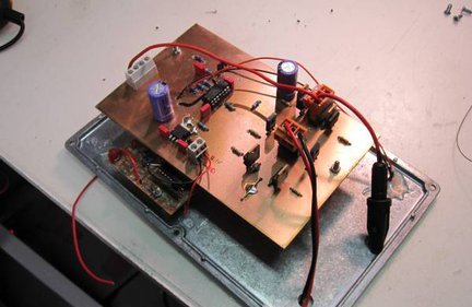
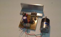
2011--Electric motor controller.
The assigment was to build a motor driver that shifted the rotation in specific sequence. It was specified for 12V and 2A. The small motor in the picture was only for testing and not the actual motor used later in the prototype.
2011--"Silent" audio amplifier.
Many years ago I built an 2,1 amplifier that I still use sometimes. It was rated 2x15Wrms and 100Wrms for subwoofer. I use this amp in my gym.
Last time i started it the subwoofer was silent. The amp is NOT service friendly and my schematics were really bad and missing a lot. It was hard to follow the signalpath due to bad documentation. Finally I revealed that a OP-circuit which was part of the subwoofer filter was dead. Changing this fixed the issue.
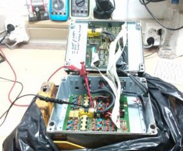
2010--Troubleshooting a motion controller.
A large construction machine was impossible to steer. A techincian identifed the controller box as faulty. It had been water damaged. The box contained two PCB's, one with mainly power electronic and one with microcontrollers. My focus was to try to refurbish the power controller card. There were several damaged components that were exchanged.
Latest news/ Archive:
2024-02-03
Devboard
2023-09-11
DIY ESD gun
2023-01-15
NanoIoT33 new rev
2022-12-12
6,5" active subwoofer
2022-10-13
Digital 2Ch amp
2022-07-30
Nano33IoT Released
2022-06-09
Nano33IoT_adapterboard
2021-10-27
IO & ADC interface
2021-09-23
Episcope
2021-09-17
Timekeeper
2021-04-03
Ljudbyggaren.se
2021-02-22
PhazeSpy
2021-02-08
PiPower
2020-12-15
New Lab
2020-06-17
Four4 usb charger
2019-03-21
Car security
2018-08-22
DIY Watchwinder
2018-05-11
GSM IO module
2017-12-06
GSM update
2017-08-23
Home diagnostics
2017-05-12
USB killer v3
2017-03-17
3D printing
2017-02-08
Signal Hound
2016-12-15
Nixie tube clock
2016-11-16
UsbSafe²
2016-10-10
Heat Chamber
2016-02-08
Kickstarter
2016-01-15
USB Fuse
2015-12-01
Volvo S60 panel
2015-19-09
801S Vibration sensor
2015-06-01
Security System
2014-12-23
3A Dummyload
2014-07-18
Simple PCB
2014-07-01
Control panel
2013-12-09
Paintball marker
2013-04-07
Remote controlled hatch opener
2012-10-12
TPA6120 Hifi headphone amplifier.
2012-04-01
Room temperature panel.
2012-02-20
Fuel Gard
2012-01-18
Powerbox repair
2011-09-17
Watchwinder
Sp-Engineering 2022